Posts: 15,300
Threads: 531
Joined: Oct 2011
City: Jackson, NJ
Kirk gave that to me to fix.
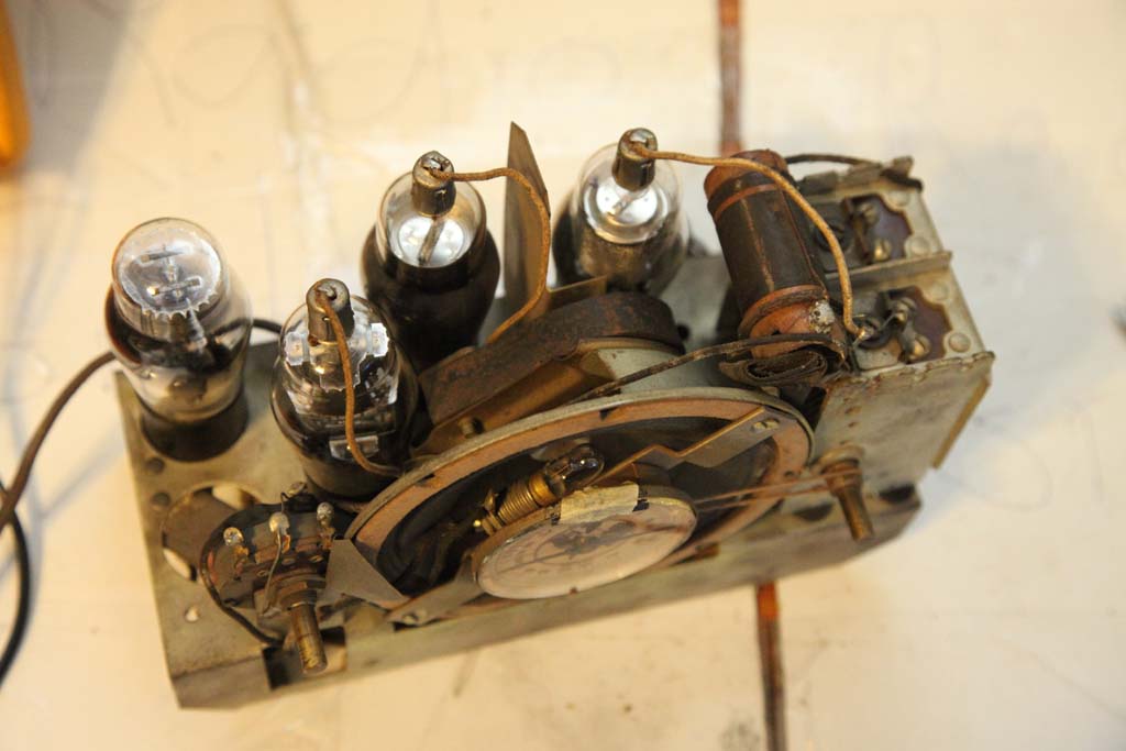
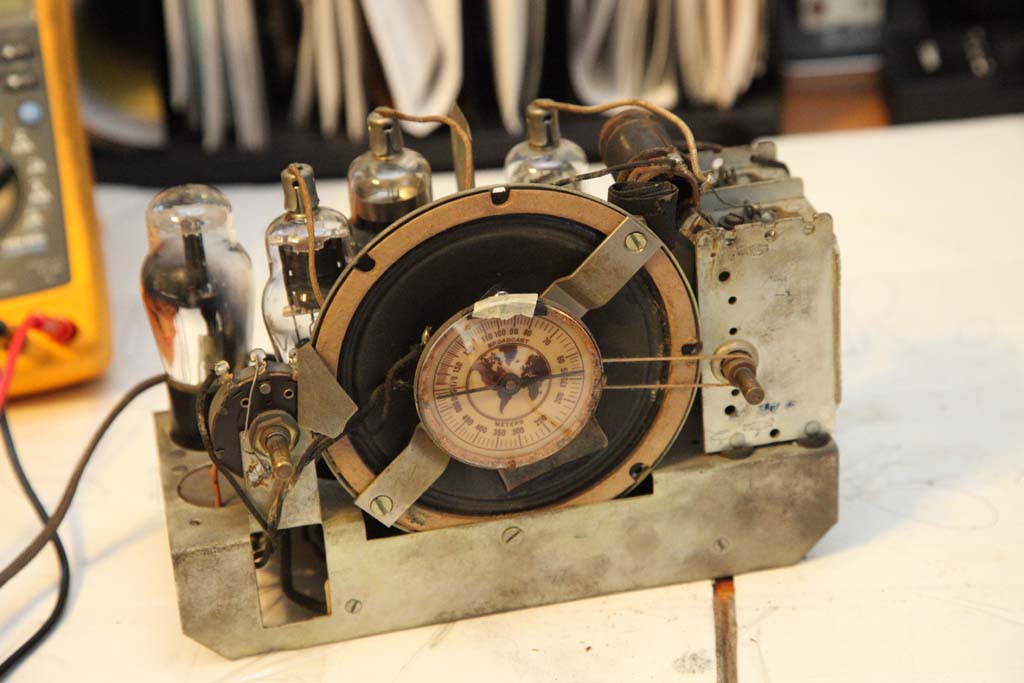
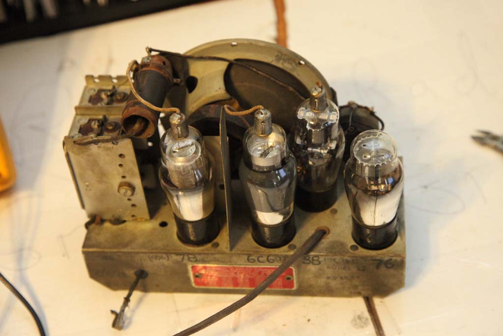
I have no idea which it is, in the Century chapter on Nostalgiaair this model does not seem to be present.
Now, after looking at the chassis it is my conclusion it is a DC model - it has no rectifier. The speaker is directly driven by the 38 tube.
It also looks like a TRF radio. Not enough coils for a superhet.
Have to wait if Kirk even wants it fixed, I am not sure he has 110V DC in his house 
Meantime,
1. what the heck is this copper ring on the power cord (in the center of the still) that is soldered to the wire and the goes to a Candohm that parallels the pilot lamp? I saw three wires coming out of 2-wire cord, cut the heatshring and this is what I saw.
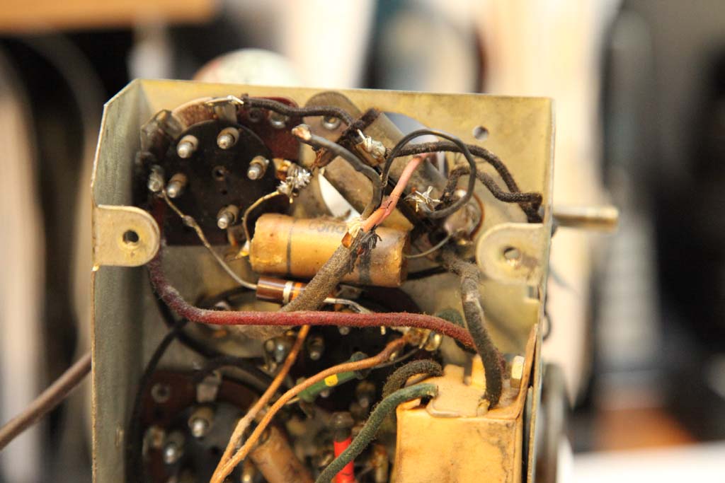
2. I take it it is filter caps. No?
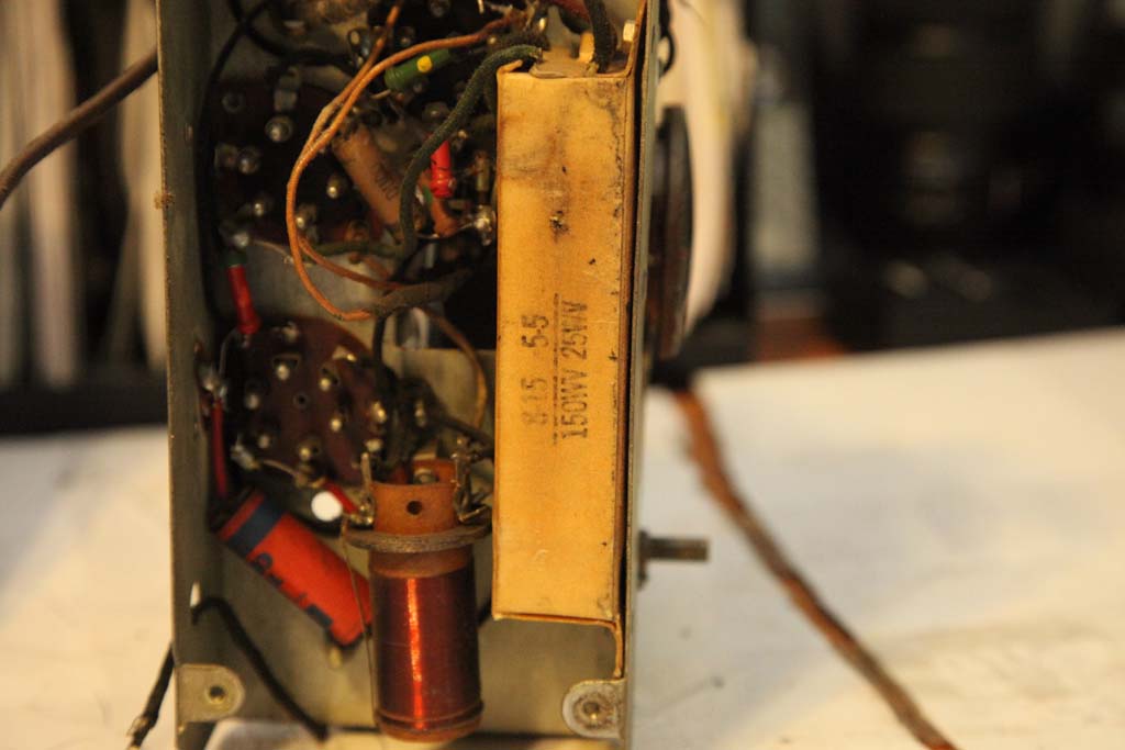
All in all, if anyone has experience with these - could use some hints.
(This post was last modified: 07-06-2014, 05:05 PM by morzh.)
Posts: 3,102
Threads: 54
Joined: Apr 2011
City: Lexington, KY
It's probably an AC/DC set that uses a resistor line cord like this Acratone with the same tube line-up:
http://www.radiomuseum.org/r/federatedp_..._25_d.html
I saw the following models that use the same tubes:
Acratone 25B
Simplex 4Z
Zephyr 4Z
I didn't the schematics listed on Nostalgia Air, but I'll check my schematics a little later and see if I can find a match.
John KK4ZLF
Lexington, KY
"illegitimis non carborundum"
Posts: 15,300
Threads: 531
Joined: Oct 2011
City: Jackson, NJ
John
no, unfortunatelybit is not.
The line cord is not resistive, both wires are regular coppers, give me more or less zero on my meter.
One of their small sets is DC only. Hot chassis, yes - one Mains lead goes via switch to the chassis.
http://www.nostalgiaair.org/PagesByModel...002647.pdf
Also how do you explain absense the of a rectifier? The tubes are all amps, no diodes.
(This post was last modified: 07-06-2014, 06:15 PM by morzh.)
Posts: 453
Threads: 29
Joined: Sep 2009
City: Lapeer
State, Province, Country: MI
Good Evening!
I would review the Simplex schematic for the 4Z and see if they match or are close. Simplex manufactured the Century and if you view the Century NTE-5 or the Simplex NT-10 at Radioattic, they have the same red patent plate. Joe
Joe
Matthew 16:26 "For what does it profit a man if he gain the whole world, yet lose his own soul?"
Posts: 15,300
Threads: 531
Joined: Oct 2011
City: Jackson, NJ
Joe
Thanks for the tip.
Nostalgia does not have 4Z, I will browse others to see if something looks similar.
The license says GE.
Posts: 1,113
Threads: 14
Joined: Feb 2013
City: Irvington, NY
Seems like the 76 triode is used as a rectifier, connected as a diode with its grid and plate tied together. Some of these small 4 tube radios did this as the DC current drain was very low.
I guess it was cheaper than using a normal rectifier tube?
Posts: 15,300
Threads: 531
Joined: Oct 2011
City: Jackson, NJ
The prong is nonpolarized...in a DC only should be polarized.
The 76 indeed looks like the grid and A are together and then K goes to this big thing which I think is the capacirive filter, so it is the B+.
OK, if it is ACDC it is good news, otherwise it makes no sense to deal with.
Thanks, John, Joe and Mondial, that's a start.
The coils are OK so hopefully once I recap and test tube....will have to recall the resistors codes, no sch to check.
Posts: 15,300
Threads: 531
Joined: Oct 2011
City: Jackson, NJ
Dummy me, the print on the stamp on the back says "110V AC-DC".
AND now that I read it gain, says "MODEL 47".
Aw'raht.
(This post was last modified: 07-06-2014, 08:10 PM by morzh.)
Posts: 1,113
Threads: 14
Joined: Feb 2013
City: Irvington, NY
Morzh, you mentioned that there were 3 wires coming out of the line cord. This certainly seems like a line cord dropping resistor. There are usually 2 copper conductors and a third wire connected to the resistance element, which is resistance wire wound around the 2 copper conductors with asbestos in between. The copper ring you described should be the termination of the resistance wire. Most likely the resistance element is now open, as they did not last long.
With only 24 v of series filaments, you have to drop almost 100 v at .3 amp, so 30 watts of heat have to be dissipated somewhere. If there are no very high wattage resistors in the chassis, then the resistance has to be provided by the line cord. That was the way it was usually done in the early midget sets.
Probably the best way to replace the filament dropping resistance is to use a series cap instead with the proper reactance to drop the 100 V. The bonus is that no heat will be dissipated, rather than the 30 W in the resistance.
Posts: 15,300
Threads: 531
Joined: Oct 2011
City: Jackson, NJ
Mondial
Yeah...ugh...yikes.
Someone could have repaced be cord as this thing was very small to dissipate anythin,g let alone 30W. Cord itsef, both wires are regular copper conductors.
So whatever that was.....it expired long time ago.
I think furst off, I need to install polarized plug, as this one is not an I think it should be.
Posts: 15,300
Threads: 531
Joined: Oct 2011
City: Jackson, NJ
OK...got it.
This is first time I see this, so....
This cord, one ofits wires has a thin wire wrapped around it AND it has 300 Ohms of resistance to the respective prong.
So, should I use it or repkace it? I can still clamp that thing.
Posts: 15,300
Threads: 531
Joined: Oct 2011
City: Jackson, NJ
OK, I think I know how to connect the filter.
The two hi volt cas go 15uF to the rect out, 8uF to SG of 38 tube, and two 5uF low volt caps go in cathode feedbacks to 38 and 6C6 tube.
Posts: 3,102
Threads: 54
Joined: Apr 2011
City: Lexington, KY
No, you don't want to use that cord, it's a fire hazard. Use some combination of a diode, capacitor, and/or resistor to drop that voltage.
John KK4ZLF
Lexington, KY
"illegitimis non carborundum"
Posts: 2,353
Threads: 92
Joined: May 2010
City: Clayton, NC
You can use a ballast tube to drop the appropriate amount of voltage, but this would involve installing another tube socket on a cramped chassis..
Another way is to use a non-polarized cap to drop the voltage .....
Posts: 2,118
Threads: 112
Joined: Jun 2010
City: Medford OR (OR what?)
Don't mess around with that cord. The 3rd wire is usually wrapped in asbestos.
"I just might turn into smoke, but I feel fine"
http://www.russoldradios.com/
Users browsing this thread: 1 Guest(s)
|


