Posts: 395
Threads: 33
Joined: Jul 2013
City: Horsham, PA
I am nearing the end of the under-chassis work on my 95. The last thing I have to do is to replace the capacitors in the condenser box (item 48 ). I disconnected all of the wires and removed the box from the chassis. It isn't clear to me how to open up this box. Here is a picture:
https://www.flickr.com/photos/104710683@...ed-public/
As you can see, there is a flange that wraps up from the bottom and extends about a half inch or so. There is one of these on the opposite side as well. Do I need to bend these away from the side? Then what? Give it some heat from the heat gun and pull it apart?
Anything else I need to do?
Thanks in advance.
(This post was last modified: 05-26-2016, 07:04 PM by
PAradiogeek.)
Posts: 16,509
Threads: 572
Joined: Oct 2011
City: Jackson
State, Province, Country: NJ
I do not remember bending anything away.
People who do not drink, do not smoke, do not eat red meat will one day feel really stupid lying there and dying from nothing.
Posts: 7,301
Threads: 269
Joined: Dec 2009
City: Roslyn Pa
Hi Jon,
I'm with Mike on this. I did my 87 two or three rs ago. I put in in the oven at about 225 degrees and I think it just pulls apart. The terminal board fits on to a track and slides out.
Terry
Posts: 395
Threads: 33
Joined: Jul 2013
City: Horsham, PA
Thanks Morzh,
Do you remember how you got it apart?
Posts: 16,509
Threads: 572
Joined: Oct 2011
City: Jackson
State, Province, Country: NJ
Well...I think there are a coupke of tabs on each side at the bottom that either snap or twistlock. I can see them on hour photo. Think they snap.
Thinking of it you need to, well, not exactly bend but gently pry the bezel away at each end to get the tabs to unsnap while pushing the bezel away from the box . Basically insert a flat screwdriver right at a tab and twist and push.
People who do not drink, do not smoke, do not eat red meat will one day feel really stupid lying there and dying from nothing.
Posts: 395
Threads: 33
Joined: Jul 2013
City: Horsham, PA
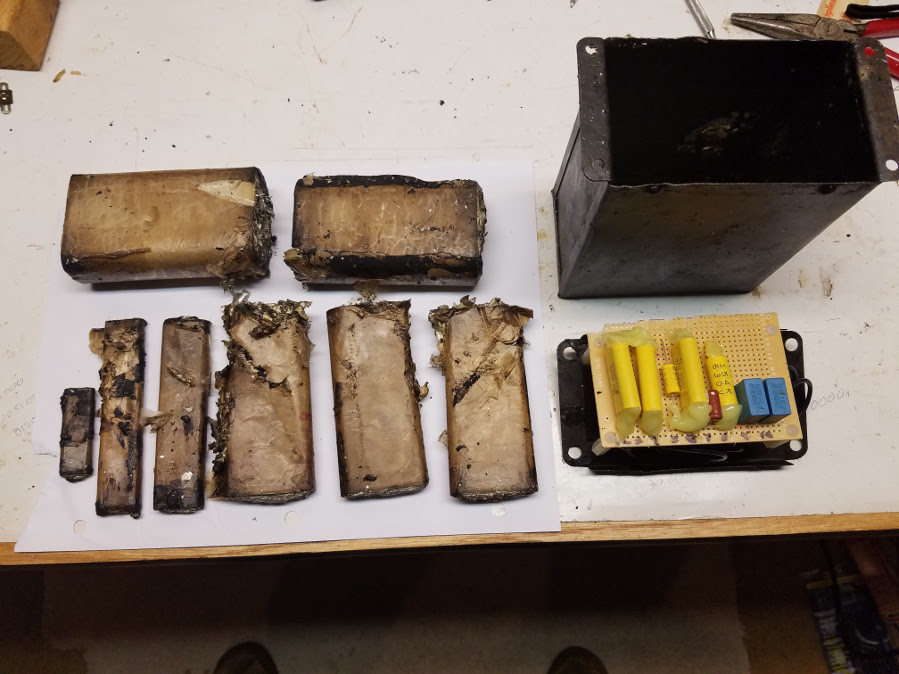
OK, thanks for the tips guys. I got it all out. Those two 2 uF caps were HUGE!!
Tomorrow I'll put the new caps in place.
Posts: 395
Threads: 33
Joined: Jul 2013
City: Horsham, PA

Here is what came out of the condenser block, and also what replaced them. Capacitor technology has advanced quite a bit in 87 years.
(This post was last modified: 05-30-2016, 12:27 PM by
PAradiogeek.)
Posts: 395
Threads: 33
Joined: Jul 2013
City: Horsham, PA
I have another question on this radio. Here is a link to the schematics for the 95 late model (
http://www.philcoradio.com/tech/images/95.jpg).
The paperwork I have on this set (from Chuck) says that this radio has AVC. To me, it looks like the AVC line starts at item #23 (0.5M resistor), and goes to the secondary of RF transformer #14. The only thing that makes me think that that line is not the AVC is that here the AVC only seems to be affecting the gain of one tube (the third and last 224 RF tube). In other sets, the AVC is usually fed to multiple RF/IF stages (I realize this isn't a superhet, so no IF).
The other option I see is that the AVC is coming off item #26 and feeding to the first two RF stages. I'm really confused by this, which is it? Or is it both?
Thanks in advance,
Posts: 7,301
Threads: 269
Joined: Dec 2009
City: Roslyn Pa
Looks like it's both. On one side it's using the detector diode to control the last RF stage and the output of the detector to control the other RF stages.
But what do I know???
Terry
Posts: 395
Threads: 33
Joined: Jul 2013
City: Horsham, PA
Posts: 7,301
Threads: 269
Joined: Dec 2009
City: Roslyn Pa
Just for grins you could measure the dc voltage on these to lines. If it varies as you tune in a strong signal that will tell the tale.
GL
Terry
Posts: 395
Threads: 33
Joined: Jul 2013
City: Horsham, PA
Good idea. I'll give it a try next time I have it on the bench. I started working on the cabinet today. I imagine that is going to keep me busy for a while.
Take care.
Jon


![[-] [-]](https://philcoradio.com/phorum/images/bootbb/collapse.png)


