Posts: 13
Threads: 3
Joined: Nov 2019
City: Morganton
State, Province, Country: Georgia USA
Hello all,
I recently purchased a 1933 Philco Model 54 AC / DC Radio. I know this set ran off 115 Volts Direct Current as well as Alternating Current years ago and Direct Current has phased out far as in home appliances. I was wondering if I could construct a DC battery and operate this radio, or is the DC that they used back then different than battery current? The set doesn't use a transformer and there is no switch to change it from AC to DC. Thanks for your help on this matter.
Keith
Posts: 7,305
Threads: 270
Joined: Dec 2009
City: Roslyn Pa
In some locations the electrical current was DC. You could run it off of batteries but compared to a set farm set which is designed to be battery powered it draws a lot of current. There is no switch because circuit doesn't care. The rectifier sees + voltage on the plate it just pass on thru and charges the filters. There's no hum filter but they don't care. It goes to the rest of the hv circuit it's all dc. The heaters are the series = 115v and guess what they don't care work fine on ac or dc. The polarity of the wall plug matters. If plugged in backwards it won't play, no harm no foul.
Now what does matter is that an AC/DC set will not have a power transformer, a volt doubler circuit, or a phono motor. All of these need ac to operate. There might be some rare case there are two power supplies in one chassis but this not the norm.
When my pals were reading comic books
I was down in the basement in my dad's
workshop. Perusing his Sam's Photofoacts
Vol 1-50 admiring the old set and trying to
figure out what all those squiggly meant.
Circa 1966
Now I think I've got!
Terry
(This post was last modified: 06-25-2022, 06:36 PM by
Radioroslyn.)
Posts: 13
Threads: 3
Joined: Nov 2019
City: Morganton
State, Province, Country: Georgia USA
Thanks for the all the great information Terry. I calculated a draw of 0.43 Amps on this set. It would drain a battery very fast indeed at that rate.
Thanks again for the reply,
Keith
Posts: 1,269
Threads: 32
Joined: Jan 2014
City: Wellborn Florida
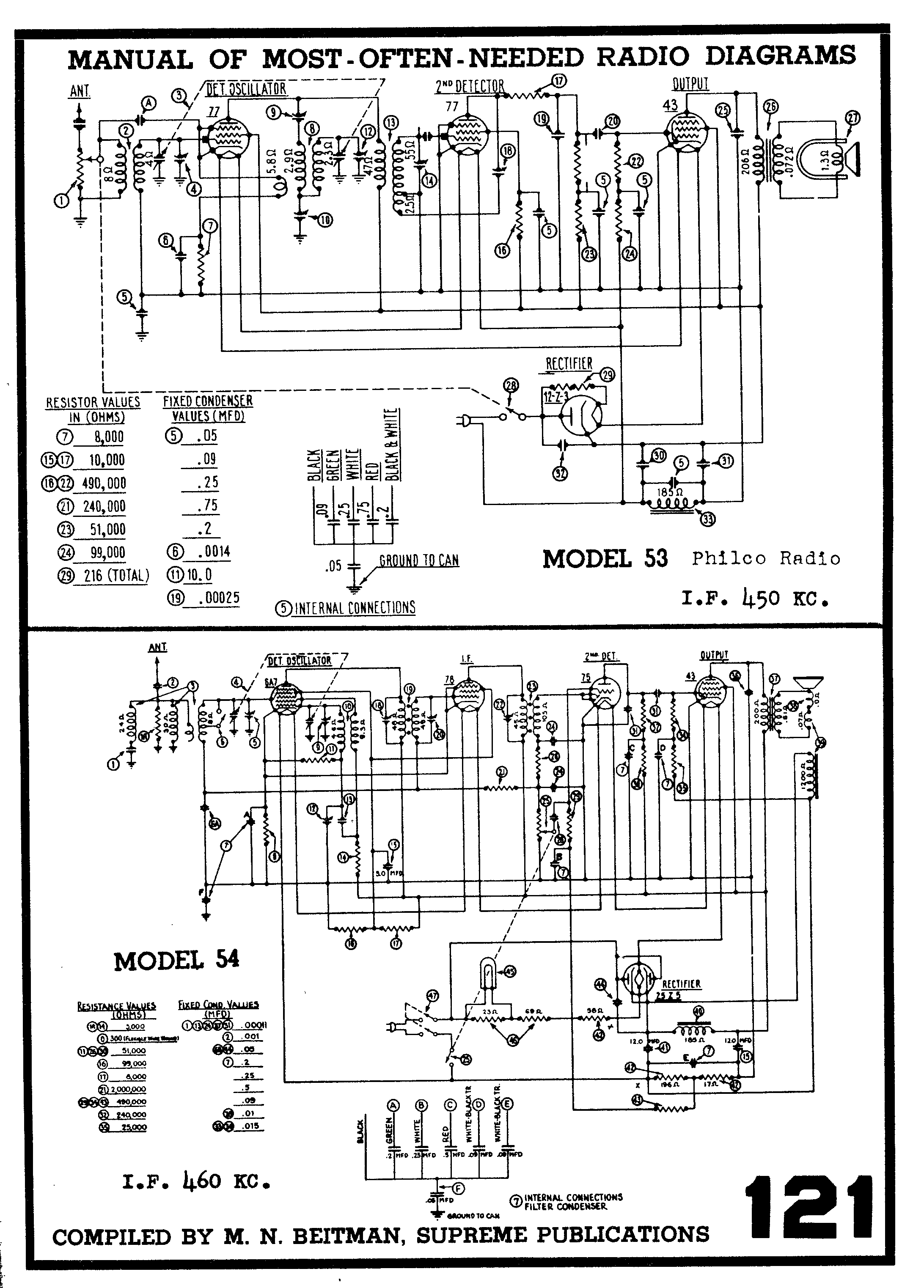
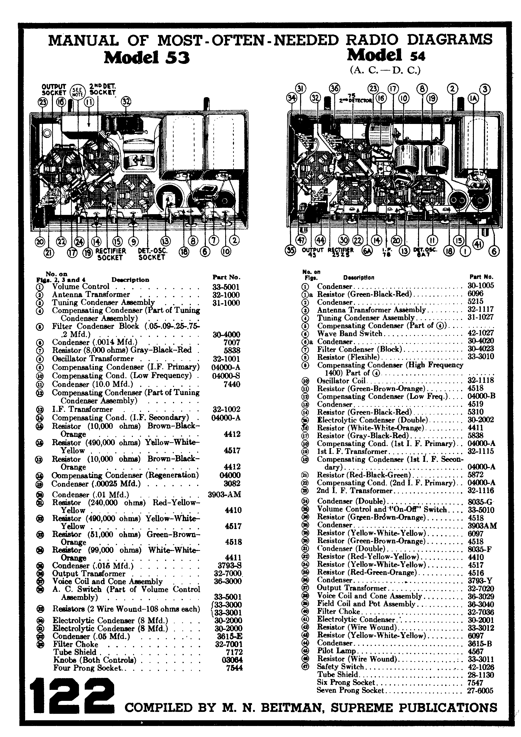
Some info from Beitmans


Posts: 13
Threads: 3
Joined: Nov 2019
City: Morganton
State, Province, Country: Georgia USA
Thanks David for the schematics.
Posts: 1,269
Threads: 32
Joined: Jan 2014
City: Wellborn Florida
A link to Frank's electron Tube Data sheets
https://frank.pocnet.net/
Posts: 13
Threads: 3
Joined: Nov 2019
City: Morganton
State, Province, Country: Georgia USA
Thanks again David.
Keith


![[-] [-]](https://philcoradio.com/phorum/images/bootbb/collapse.png)


