Posts: 45
Threads: 6
Joined: Apr 2023
City: Temecula
State, Province, Country: CA
Not sure it's practical with the typical consumer radio... but does anyone attempt to "improve" on the chassis wiring with neater wire routing and cabling?
Or do you stick to the original rat's nest for authenticity?
Related comment for other beginners like me: The schematic does NOT necessarily correspond to the actual wiring! It may be electrically identical, but it doesn't depict the actual wiring connections.
A common example: Those Philco Bakelite capacitor blocks are often a single 2-lead cap... but the block has eight tie points! So the unconnected middle set may just be a convenient tie point for a wire on the way to somewhere else, while you may be scratching your head wondering why THAT wire connects to THIS cap... it doesn't.
Another example: You'd think the 4-pin jack to the speaker assembly would be shown somehow on the schematic... not on mine. One needs to suss out where the connections are.
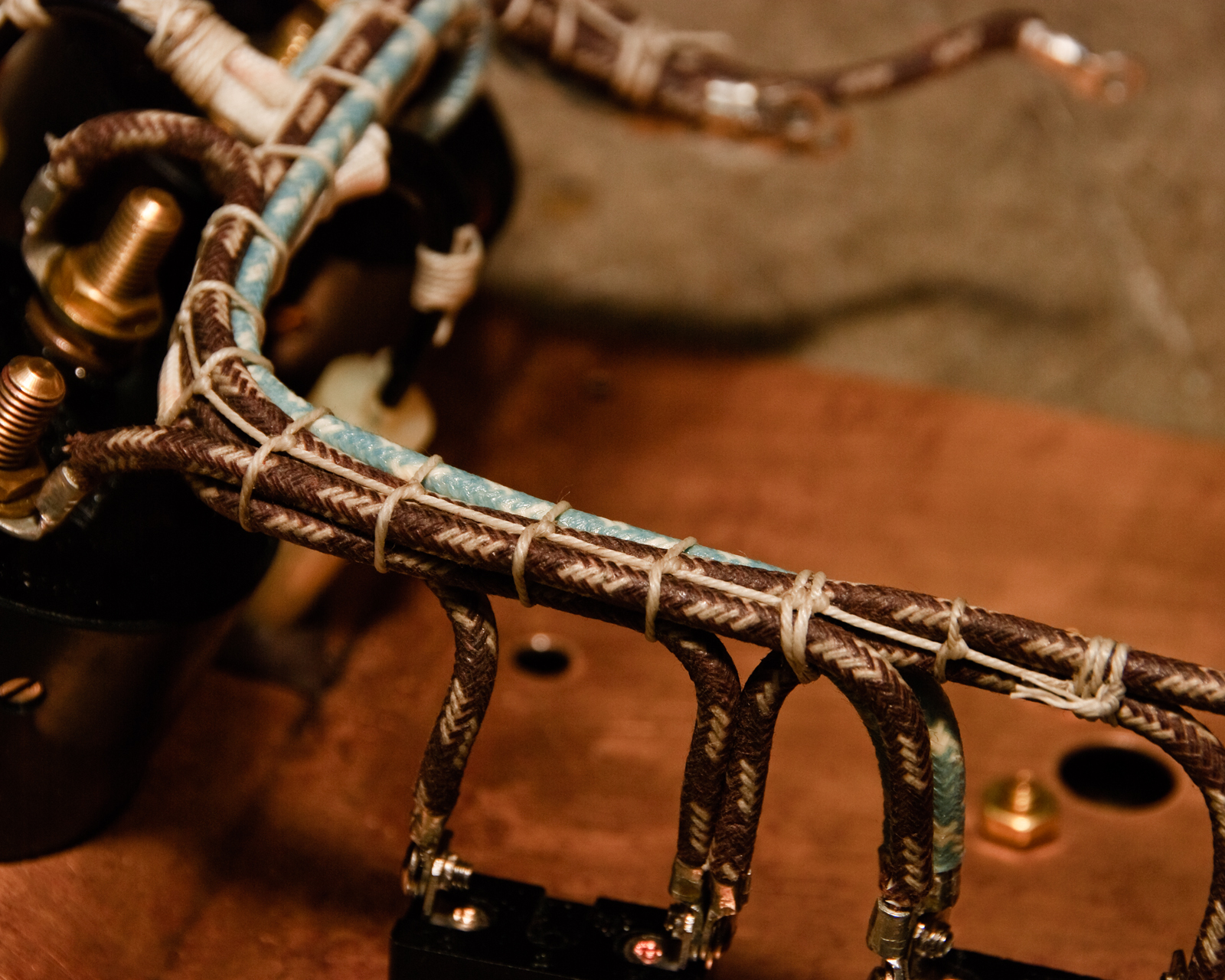
Ah, cable lacing:
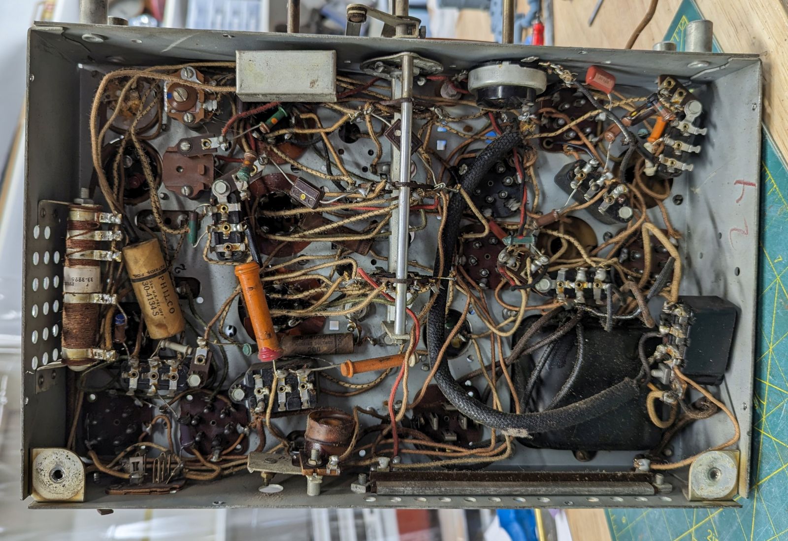
A rat's nest:
(This post was last modified: 04-21-2023, 12:16 PM by patmat2350.)
Posts: 2,263
Threads: 164
Joined: Jan 2013
City: Westland, MI
Simple answer ... if it ain't broke don't fix it, and don't re-route it from its' original placement. Address any frayed or rodent-chewed wiring only. Rerouting to a more 'pleasing' look can sometimes introduce signals that were originally routed to shield against. Cloth wire holds up well for its' years in most cases. Take care and BE HEALTHY! Gary
"Don't pity the dead, pity the living, above all, those living without love."
Professor Albus Dumbledore
Gary - Westland Michigan
Posts: 45
Threads: 6
Joined: Apr 2023
City: Temecula
State, Province, Country: CA
Speaking of shielding ... my radio has a shielded cable from the line filter cap to the power switch on the other side of the chassis. The shield is only soldered at one end, near the line filter. I assume this is useful?
This cable is on my list, as it's hard and crackly.
Posts: 45
Threads: 6
Joined: Apr 2023
City: Temecula
State, Province, Country: CA
And another Q on this subject:
I see a number of sources for new cloth covered wire...all in solid colors. No one has the ticked cloth (spots of color)?
Posts: 13,776
Threads: 580
Joined: Sep 2005
City: Ferdinand
State, Province, Country: Indiana
+1 what Gary said.
The shielded cable was put there in an effort to reduce the possibility of AC hum being introduced into the radio (chiefly, the audio) circuitry. And it was grounded only on one end because that was all that was needed - if it is grounded on one end, it is grounded through its entire length.
As to cloth covered wire with different color tracers (or, in your words, "ticked") - the answer is no, not in the size typically used in vintage radios (20 gauge).
--
Ron Ramirez
Ferdinand IN
Posts: 1,418
Threads: 41
Joined: Jan 2014
City: Wellborn Florida
Be careful trying to improve wiring! Look at a hallifcrafters S38A-S38E and see how they got the BFO. https://philcoradio.com/phorum/showthrea...6#pid91506
Posts: 18,427
Threads: 622
Joined: Oct 2011
City: Jackson
State, Province, Country: NJ
At best you will not have problems.
Wires, especially carrying AC signals (most do) do not like long parallel runs. Point to point routing provides for shortest runs and in most cases criss-crossing ones, which is good for fighting off interference.
So....it's your radio, but the best you can possibloy do is to stick to the original, in every aspect possible.
People who do not drink, do not smoke, do not eat red meat will one day feel really stupid lying there and dying from nothing.
Posts: 2,327
Threads: 23
Joined: Jul 2020
City: Greenlawn
State, Province, Country: NY
+1 on Gary, Ron R and others. The reason that the shield is grounded on one side only is to prevent ground loops (the shield acting like the secondary of a transformer).
We often specified a "wired ground" instead of using the conduit as a ground in some of our analyzer installations (These systems were sensitive to poor grounds). To prevent aggravation by ground loops, an "isolated ground" outlet was used where the ground pin was not connected to the outlet frame. This way, a solid, quiet ground could be obtained (assuming that the subpanel was quiet.
"Do Justly, love Mercy and walk humbly with your God"- Micah 6:8
"Let us begin to do good"- St. Francis
Best Regards,
MrFixr55
Posts: 1,418
Threads: 41
Joined: Jan 2014
City: Wellborn Florida
The term quiet grounds brings back memories from working at the paper mill. If some fool tried to strike a arch and used the buildings I Beams for a welding ground the control systems would go Bat $#@ crazy. The place had miles of 0000 copper cable for welding grounds.
Users browsing this thread:
|
|
Recent Posts
|
|
Philco 71 Code 125
|
| Hello,
I am in need of a schematic for this radio. Mine has the three separate circular tube shields and a shadow me...dconant — 08:06 AM |
|
Stromberg Carlson 1500 Squeal
|
| And life just keeps getting more complicated.dconant — 07:57 AM |
|
54C Complete Teardown/Rebuild
|
| Hello Roy,
here is this one
sincerely Richardradiorich — 12:45 AM |
|
54C Complete Teardown/Rebuild
|
| Richard,
Had grabbed it already but thank you just the same. I find myself wanting to find some way to block out the...glyphmon — 12:03 AM |
|
54C Complete Teardown/Rebuild
|
| Hello roy,
here is a link to the schematic .
Sincerely Richardradiorich — 11:54 PM |
|
54C Complete Teardown/Rebuild
|
| Richard,
The Silvertone 2014 also is a transformerless set, so I am incorporating a 1:1 600 ohm audio isolation transfo...glyphmon — 11:37 PM |
|
Preliminary work on wife's Silvertone 2014
|
| Did an alignment today which was interesting. IF alignment went great, almost all was already spot-on. Adjusting on th...glyphmon — 11:35 PM |
|
54C Complete Teardown/Rebuild
|
| The main problem with adding a Bluetooth input is that this set lacks a traditional power transformer to isolate it from...radiorich — 11:19 PM |
|
54C Cabinet Refinish
|
|
I started stripping this cabinet before it got super chilly out because I knew I wasn't going to be able to work on ...glyphmon — 11:18 PM |
|
54C Complete Teardown/Rebuild
|
| While I'm waiting to wrap up the final steps on my wife's Silvertone 2014, I started disassembly on the next project. O...glyphmon — 11:07 PM |
|
Who's Online
|
There are currently 1520 online users. [Complete List]
» 4 Member(s) | 1516 Guest(s)
|
|
|

|
 
|










