Posts: 122
Threads: 37
Joined: Jul 2012
City: Coral Springs, FL

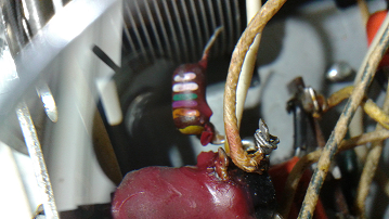
Hi. Please see attached photo of a capacitor. Can someone possibly tell me what the capacitance is on this one?
I'm not sure if this is a paper cap or a mica cap. It's from a 1954 Philco radio model B 1750. It's shaped like a kidney bean, not like any of the other paper or mica capacitors in the radio. The tip of one side is yellow, then the stripes are:
orange, violet, green, white, white.
The schematic says it is 7.5 pf (mmf) - just want to confirm this is what the capacitor is saying. Thanks
Posts: 16,579
Threads: 574
Joined: Oct 2011
City: Jackson
State, Province, Country: NJ
Well, purpe and green are 7 and 5.
Judging by that it is likely 7.5pF.
Now this capacitance is not likely to be paper.
It is either mica or ceramic, given the 50s, likely the former.
Posts: 1,411
Threads: 71
Joined: Oct 2007
City: Linn Creek, MO
I wouldn't change it unless you are sure it is bad.
Steve
M R Radios C M Tubes
Posts: 16,579
Threads: 574
Joined: Oct 2011
City: Jackson
State, Province, Country: NJ
Exactly. Micas are fine unless you troubleshoot and find them misbehaving. It is paper and lytics that have to go.
Posts: 122
Threads: 37
Joined: Jul 2012
City: Coral Springs, FL
This cap reads 18 pf on my meter -so if it's supposed to be 7.5pf, then I guess it's gotta be replaced. Thanks for everyone's help. [Image:
http://philcoradio.com/phorum/images/smi..._angel.gif]
Posts: 16,579
Threads: 574
Joined: Oct 2011
City: Jackson
State, Province, Country: NJ
What meter do you have?
before you discard anything, measure your leads' capacitance; it very well might be you are measuring them plus your cap.
Posts: 122
Threads: 37
Joined: Jul 2012
City: Coral Springs, FL
Meter is a New Cason XC6013-L. You are EXACTLY right. If I measure the capacitor by putting the probes right next to the capacitor - it reads 7.4 pf - (should be 7.5) but is well within tolerance. Never new that where you put the probes on the leads can make a difference. Live and learn. Thanks,
Posts: 348
Threads: 48
Joined: Oct 2013
City: Tioga, Texas, USA
Yes, small value (less than 100pFd) capacitors have to be measured very carefully, often it becomes necessary to remove from circuit and use the shortest leads possible. Any lead capacitace value needs to be zeroed out before measuring the capacitor. That particular cap may be a tubular ceramic that has been dipped in an epoxy coating, then painted. There were a number of low value capacitor types used in that era.
Joe


![[-] [-]](https://philcoradio.com/phorum/images/bootbb/collapse.png)


