Welcome Guest! Be sure you know and follow the Phorum Rules before posting. Thank you and Enjoy! (January 12) x

Thread Closed
Thread Rating:
  • 0 Vote(s) - 0 Average
  • 1
  • 2
  • 3
  • 4
  • 5

GE A-70 vernier operation
#1

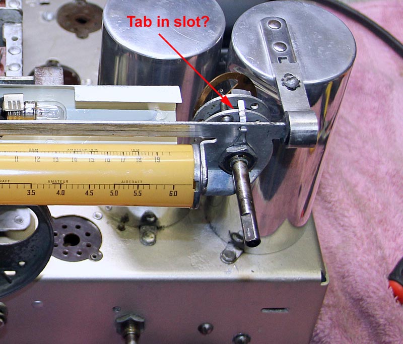
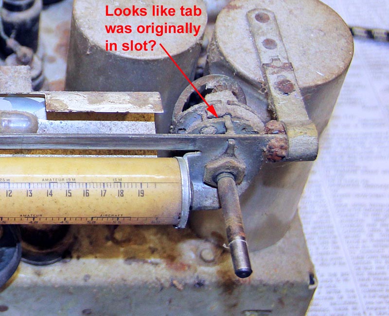
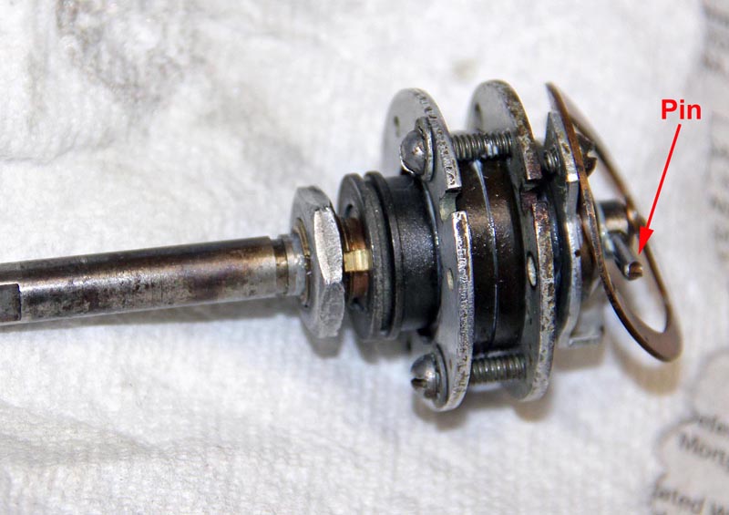
I am having trouble understanding the operation of the vernier control on my GE A-70. I took it apart and cleaned, lubricated it and re-installed it with along with re-stringing the rotating dial. Everything works great except the pointer does not move during fine adjustment. There is only one shaft which I think should automatically switch from fine to coarse when the pin hits the stop on the rear of the control (I attached photos showing the pin and tab).

If I place the tab on nut into the slot on the front of the vernier it prevents the control from switching to coarse and limits the dial travel.  However it appears from my photo of the original set up that the tab is in the slot so I am confused. can anyone shed some light on how this control is supposed to be set up.

Thanks,

Steve D
           
#2

The tab does look like it belongs in the slot. I see a snap ring in the original photo. Was that just holding what appears to be a dust cover or is something possibly missing?
#3

Thanks for you response. I don't see a snap ring and don't remember one when I took it apart.  What appears to be a dust cover I think was actually some dust itself.  The whole vernier was clogged up with dust.

Steve D
#4

I solved this issue by adjusting the three clamping screws to get the proper preload on the ball bearings. I had the screws tightened down too much. The tab does indeed need to be in the slot to prevent rotation of the vernier body and then the screws adjusted for proper operation. This vernier control is intuitive and works very well when adjusted properly.

Steve D


Users browsing this thread: 1 Guest(s)
[-]
Recent Posts
Restoration of the Canadian General Electric A-87
Well... The console body has been restored, while the varnish dries reliably I started repairing the chassis.. ...RadioSvit — 07:12 AM
Philco Model 38-7: what caps & resistors do fail typically?
Hello Martin, Welcome aboard our little community what great Model 38-7 Sincerely Richardradiorich — 12:30 AM
Philco Model 38-7: what caps & resistors do fail typically?
Welcome to the Phorum Martin. I count about 9 paper caps, the 3 electrolytic caps and 2-Y2 safety caps to replace th...RodB — 09:44 PM
Part numbers to model cross
Jim, We have this index put together by Dale Cook but I don't think that is quite what you are looking for. The Parts...klondike98 — 09:37 PM
Philco Model 38-7: what caps & resistors do fail typically?
Yep the dim bulb test is OK but I'd definitely replace all those electrolytics before I did it. Since those #47 conden...klondike98 — 09:18 PM
Philco 42-345 Restoration/Repair
The resistor is a 2.2 Meg, it was the last one I hadn't replaced. The broadcast is coming in after replacing it.osanders0311 — 09:09 PM
Philco 42-345 Restoration/Repair
What does the resistor measure? I think it should be 3.3 Meg. If the oscillator coil has continuity and the resistanc...RodB — 09:03 PM
Philco Model 38-7: what caps & resistors do fail typically?
Good idea to check the coils... then I'll get hold of an incadescent light bulb and see what happens when the unit is sw...Musaeum — 08:49 PM
Philco 42-345 Restoration/Repair
I have that same set, ain't too much shortwave I like anyway.....it is a good AM DX set. PaulPaul Philco322 — 08:32 PM
Philco Model 38-7: what caps & resistors do fail typically?
Welcome to the Phorum, Martin! Open a new thread in Philco Electronic Restoration when you begin working on your 38-7. ...GarySP — 08:28 PM

[-]
Who's Online
There are currently 781 online users. [Complete List]
» 2 Member(s) | 779 Guest(s)
AvatarAvatar

>