Posts: 1,262
Threads: 32
Joined: Jan 2014
City: Wellborn Florida
Purchased this radio in 2006 never could get it to work right. When I get in the mood I will do some more work on this thing. All caps and out of spec resistors replaced. First thing never use a AAA battery for A battery for testing. This set likes a couple of D cells to supply 1.5 volts for the A battery. For the B battery using the power supply design on Phils old radios web site.
http://antiqueradio.org/bsupply.htm The no load voltage 94VDC with radio on reads 84-83VDC. Replaced the fellowing tubes with NOS 1H5GT, 3Q5GT all other tubes checked by using NOS sub no change in performance. Replace the speaker and output transformer the orginals were trash. Now to the problem if I connect a ground get a very loud buzzing sound. If I disconnet the outside ant coil from the chassie and use a ground to the outside ant coil big improvment in reception.
http://www.nostalgiaair.org/Resources/231/M0011231.htm At this point very happy with the radio just do not understand what is happening with the ground. David
Posts: 1,114
Threads: 14
Joined: Feb 2013
City: Irvington, NY
If you are using the power supply design shown in the Phils Radios link without an isolation transformer, you have created a very dangerous condition.
The ac line is directly connected to the radio chassis, so connecting the radio to an external ground is a problem. You have created a hot chassis set. Do not connect anything external to the radio without an AC isolation transformer!
Read the caution in the power supply instructions regarding the use of an isolation transformer. Its the only safe way to use this power supply with external antenna and ground connections.
Posts: 1,262
Threads: 32
Joined: Jan 2014
City: Wellborn Florida
Thanks for the warning, so this thing is going to try and kill me. David
Posts: 1,262
Threads: 32
Joined: Jan 2014
City: Wellborn Florida

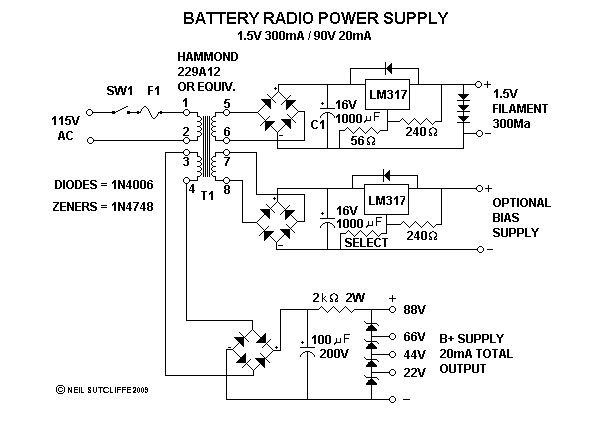
I would like to build a better power supply that does not require a seperate isolation transformer. The one I am building for the A battery supply contains a LM317 showing three diodes on the output instead of a small cap? Could someone please explain this to my simple mind. David
Posts: 1,114
Threads: 14
Joined: Feb 2013
City: Irvington, NY
The diodes are most likely there for protection.
If the regulator LM317 should short, it would put the full unregulated DC voltage into the 1.4V filaments of the tubes, instantly blowing them out. The three diodes effectively clamp the output voltage to a max of 2V or so, thereby protecting the filaments from possible destruction in case of regulator failure.
Posts: 1,208
Threads: 85
Joined: Jan 2014
City: Annapolis, IL
State, Province, Country: USA
I think Phil's power supply would be ok for portable radios that are in plastic cabinets an such. I believe this is what it is designed for. In the older wooden cabinet radios, there are exposed chassis, screws, maybe knobs with set screws that you could touch. Probably not a good idea to use next to the bathtub.

Polarized plug would help, but Mondial is right in that you could have a hot chassis. Depends on how the plug is connected.
If I could find the place called "Somewhere", I could find "Anything"

Tim
Jesus cried out and said, "Whoever believes in me , believes not in me but in him who sent me" John 12:44
Posts: 1,824
Threads: 114
Joined: Jul 2014
City: Sneedville, TN
David, if you are building the supply in the schematic you posted, I see nothing wrong with it, really. All the voltages to the radio itself are isolated by being separate windings on the transformer.
Posts: 22
Threads: 2
Joined: Mar 2016
City: Canyon Country CA
I have several farm sets, including a Motorola and, *gasp* a Philco! With both of these, I use a string of 8 to 10 nine volt batteries for the plate circuit, and one D cell for the heaters.
Connected to my outdoor random length long wire antenna which uses RG59 coax as the lead in, I get no household AC interference; great for DXing!


![[-] [-]](https://philcoradio.com/phorum/images/bootbb/collapse.png)


