Posts: 1,531
Threads: 242
Joined: Sep 2012
City: West Bend, Wisconsin
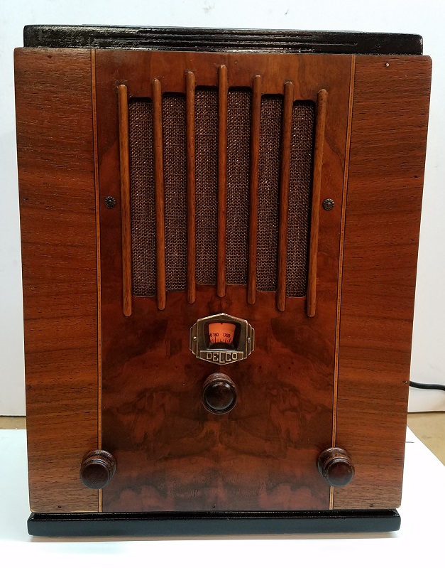
I picked up a small tombstone Delco radio at the last WARCI meet earlier this month rather inexpensively. It's a 1935 model R3202:
http://www.nostalgiaair.org/pagesbymodel...022381.pdf
I picked it up mainly because I have an extra power supply (thanks to Terry ; see thread
http://philcoradio.com/phorum/showthread.php?tid=15152 ) that steps down 120VAC to the proper 32 VDC to operate the radio.
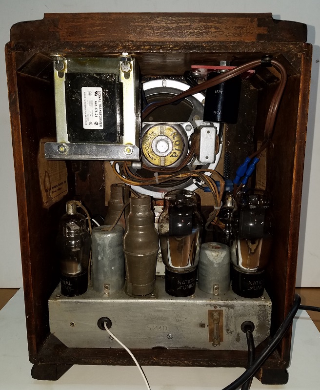
The problem I've encountered is an open primary on the detector coil. Number 6 on the schematic. It is not a straight forward coil with two distinct windings, but rather has a wire running up through the tube, out a hole in the side, around a couple of turns, back through the hole, down to the other end. In other words, it would be very difficult (for me anyhow) to rewind properly. The secondary measures 11 ohms, but I have no idea what the primary should be.
Is there such a thing as a universal replacement detector coil, like AES offers for the OSC and ANT coils?
Greg V.
West Bend, WI
Member WARCI.org
Posts: 7,301
Threads: 269
Joined: Dec 2009
City: Roslyn Pa
Depends you could add a 10K or so resistor across the primary and a cap (50-100mmf) from the plate of the 6d6 to the top of the secondary winding. Or you could replace it w/one of these:
https://www.tubesandmore.com/products/coil-rf
When my pals were reading comic books
I was down in the basement in my dad's
workshop. Perusing his Sam's Photofoacts
Vol 1-50 admiring the old set and trying to
figure out what all those squiggly meant.
Circa 1966
Now I think I've got!
Terry
Posts: 1,531
Threads: 242
Joined: Sep 2012
City: West Bend, Wisconsin
Thanks for the idea, Terry. After replacing the antenna coil....which also had an open primary....with a similar antenna coil I had in my parts stash, we tried a 10K resistor and an 85 mmf cap (you said 50 - 100 mmf), connected as you said. The radio now receives the local station (1470) loud and clear, and other stations along the dial down to 920. Below that I don't receive anything. I should get 620 AM blaring, as that's the powerhouse station out of Milwaukee.
Do you think going higher or lower with the value of the 10K resistor would help find the lower end of the dial (or likewise with the mmf cap)? I haven't yet attempted an alignment, which also could have an effect. Right now the detector coil is out of the chassis and gator wired in (along with the resistor and mmf cap).
Greg V.
West Bend, WI
Member WARCI.org
Posts: 7,301
Threads: 269
Joined: Dec 2009
City: Roslyn Pa
< Right now the detector coil is out of the chassis and gator wired in (along with the resistor and mmf cap).
The coil (secondary) needs to be in the circuit. It tunes the input of the mixer. The primary isn't it's just there to transfer the rf signal to the secondary and then to the mixer input.
On second thought 10K might be a little high, I was thinking that this set has a more normal B voltage like 200v but it doesn't it's 30v. So lowering the resistance could be a good idea. Try around 2-5K. For best results leave the coil in the chassis and solder the resistor and cap across the coil's terminals. Adding clip leads and such changes it's characteristics.
At best using the resistor and cap is a work around but not as efficient as a rf transformer. The link I sent you to the replacement coil is a good substitute. It's also slug tuned so you set the tracking (assuring that the rf gain is even across the entire band). What you would do is you adjust the slug for the best sensitivity @ the low end and the trimmer @ the center of the tuning cap for the high end. There probably be some interaction so you should do this adjustment a couple times.
Out here in the east I rarely see any 32v sets.
When my pals were reading comic books
I was down in the basement in my dad's
workshop. Perusing his Sam's Photofoacts
Vol 1-50 admiring the old set and trying to
figure out what all those squiggly meant.
Circa 1966
Now I think I've got!
Terry
(This post was last modified: 05-28-2018, 11:58 AM by
Radioroslyn.)
Posts: 1,531
Threads: 242
Joined: Sep 2012
City: West Bend, Wisconsin
Thanks again, Terry. I know that gator wiring anything in isn't ideal or the way to go. We removed the coil just to see if we could find the break. I have one of the AES RF coils you recommended on order so hopefully that will do the trick. Will keep you posted.
Greg V.
West Bend, WI
Member WARCI.org
Posts: 1,531
Threads: 242
Joined: Sep 2012
City: West Bend, Wisconsin
Success! Got it working again. Thanks, Terry. Much appreciated. The radio was a bit of a surprise, to me at least. There are no electrolytics, and the ground wire doesn't go directly to chassis ground, but goes to a .25 mfd cap first...the largest value cap in the set. Odd too that for a 32 volt farm radio they'd have two 6D6's and two 48's. Seems like a lot for a little one band 6 tube set! But it turned out decent. It was a $20 purchase and was in filthy shape when I got it. Full of mud and mouse nests. Mickey had quite a feast on the cloth wires too!


Greg V.
West Bend, WI
Member WARCI.org


![[-] [-]](https://philcoradio.com/phorum/images/bootbb/collapse.png)


