Posts: 1,544
Threads: 243
Joined: Sep 2012
City: West Bend, Wisconsin
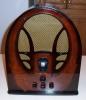
I'm working on a slant front model 39-30 and found that someone replaced the original FC speaker with a permanent magnet. The resistor they used in place of the FC seems way too much.... it's a 10K resistor. What should the FC measure on a 39-30? I'm not finding it on the schematic.
https://philcoradio.com/library/download...20Book.pdf
As it stands I'm only getting the local station through faintly at full volume. Going to check voltages tomorrow night but am wondering if that large resistor could be at least part of the trouble.
Greg V.
West Bend, WI
Member WARCI.org
Posts: 935
Threads: 142
Joined: Mar 2015
City: Lansdale
State, Province, Country: PA
The resistance is lower right corner of schematic.. Right under IF= 470KC in a Box.. Says 2000 Ohms for a 39-30
Skip...
Posts: 7,323
Threads: 270
Joined: Dec 2009
City: Roslyn Pa
If the coil is replaced w/ a 10k resistor you are going to have a 300v drop from the cathode of rectifier to the screen grid of the 41 (output of the power supply) in rough numbers. Equaling abt 5v B+. @ 2000ohms you'll have abt a 100v drop which is pretty close to what the pin voltages equal.
When my pals were reading comic books
I was down in the basement in my dad's
workshop. Perusing his Sam's Photofoacts
Vol 1-50 admiring the old set and trying to
figure out what all those squiggly meant.
Circa 1966
Now I think I've got it!
Terry
Posts: 1,544
Threads: 243
Joined: Sep 2012
City: West Bend, Wisconsin
Thanks, Skip, it was there but I somehow overlooked it.
Terry: I changed the 10K resistor to a 2K , 10 watt. No change in the faint reception of one station. Checked some voltages and found I have ZERO volts on the plate of the 78 tube. I checked the ANT coil and the OSC coil and they are both good. Checked the 1st IF can and am getting the correct readings there too.
Greg V.
West Bend, WI
Member WARCI.org
Posts: 7,323
Threads: 270
Joined: Dec 2009
City: Roslyn Pa
At face value it would seem that the primary of the second IF transformer is open or has no voltage feeding it. Perhaps a shorted piece of shorted rubber wire.
When my pals were reading comic books
I was down in the basement in my dad's
workshop. Perusing his Sam's Photofoacts
Vol 1-50 admiring the old set and trying to
figure out what all those squiggly meant.
Circa 1966
Now I think I've got it!
Terry
(This post was last modified: 04-02-2019, 07:40 PM by
Radioroslyn.)
Posts: 1,544
Threads: 243
Joined: Sep 2012
City: West Bend, Wisconsin
Bingo! You nailed it Terry. Open primary on the 2nd IF transformer. I removed the can and checked it again, it's definitely an open coil, not a shorted wire. That's a first for me, an open IF transfomer. Wonder what caused the failure.
So...this has me digging through my parts boxes. I parted out a 1941 Philco console chassis with a similar tube count years back and I THINK I found a suitable IF can that I can use. It has the 51K resistor inside, and the two small value capacitors. The primary and secondary ohm values are a bit off, but not drastically. At this point, I have nothing to lose trying it. The original would need to be rewound and I have never tackled rewinding an IF transformer before. Rewinding the ANT and OSC coils were bad enough on the model 89 and 84's I've worked on!

Will tackle installing it tomorrow night after the daily work grind. Stay tuned...I hope I will be able to with this IF can!
Greg V.
West Bend, WI
Member WARCI.org
Posts: 7,323
Threads: 270
Joined: Dec 2009
City: Roslyn Pa
>The primary and secondary ohm values are a bit off,
Doesn't matter at all but the resonant frequency does. According to the diagram the original as those two caps and resistor in it too aka avc filter. IF coils generally are a different animal by comparison to rf coils. A lot more turns as the frequency is much lower and different wire (litz) to develop higher Q. Physical size and placement are somewhat critical too as it can effect the gain and selectivity.
When my pals were reading comic books
I was down in the basement in my dad's
workshop. Perusing his Sam's Photofoacts
Vol 1-50 admiring the old set and trying to
figure out what all those squiggly meant.
Circa 1966
Now I think I've got it!
Terry
Posts: 1,544
Threads: 243
Joined: Sep 2012
City: West Bend, Wisconsin
Success! The replacement IF can from the parted out chassis worked like a charm

It receives stations up and down the dial as it should. Lots of volume and sensitivity.
I got lucky. Very lucky.

Greg V.
West Bend, WI
Member WARCI.org