

12-31-2019, 03:51 PM
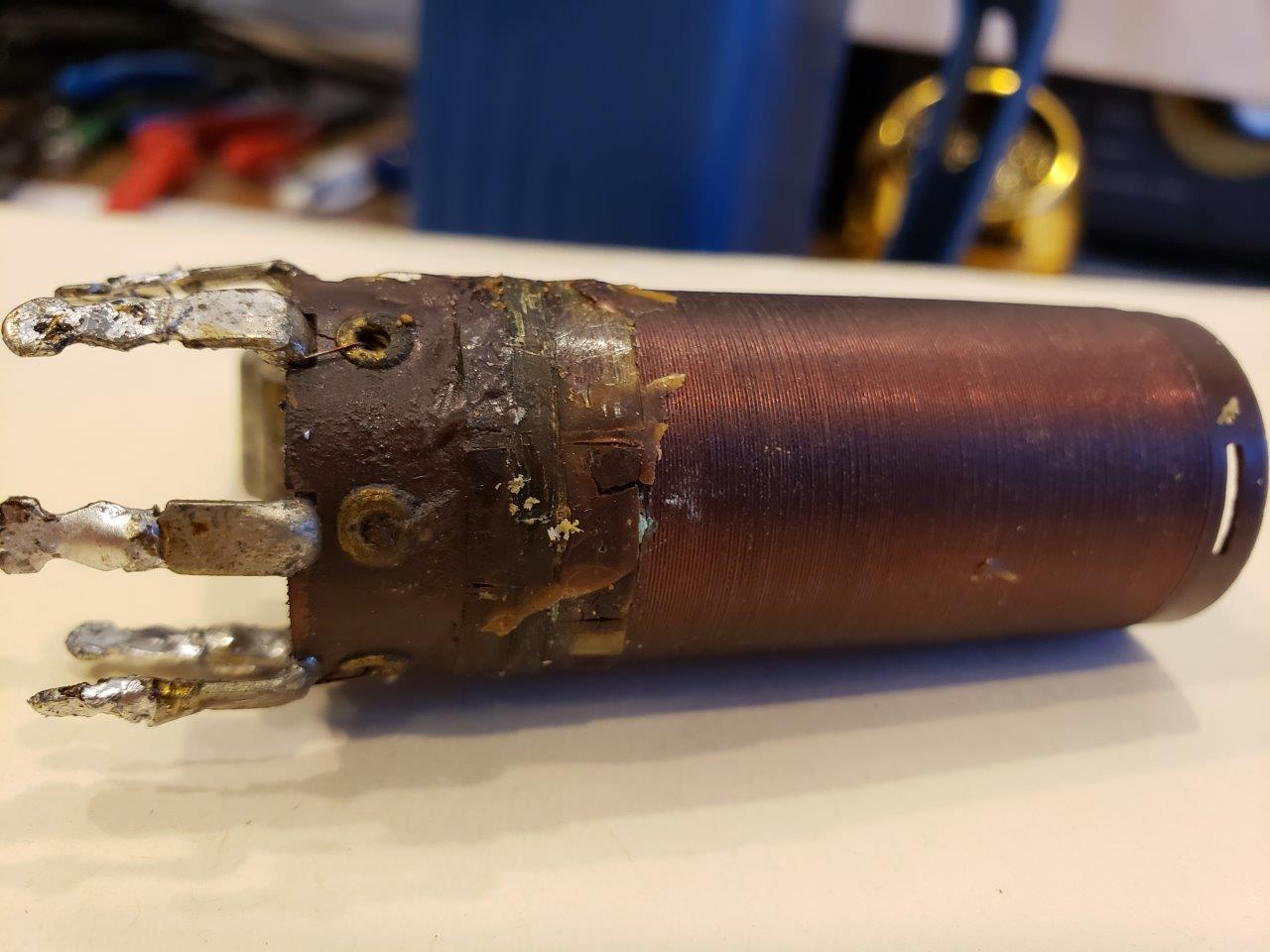
Gentlemen; this "Detector Transformer" coil is broke: how to get that waxy stuff off, without damaging the wire any further please?

|
Philco 19 Code 128

12-31-2019, 03:51 PM
Gentlemen; this "Detector Transformer" coil is broke: how to get that waxy stuff off, without damaging the wire any further please?

12-31-2019, 04:19 PM
Heat gun works for me. Get it hot and you can wipe it off w/a rag.
When my pals were reading comic books I was down in the basement in my dad's workshop. Perusing his Sam's Photofoacts Vol 1-50 admiring the old set and trying to figure out what all those squiggly meant. Circa 1966 Now I think I've got it! Terry 
12-31-2019, 06:54 PM
No need to worry about the outer winding, you will need to replace it any way. Unwind the outer winding and use your finger nail to scrape off the plastic. Then, as Terry said, use a heat gun and a rag to remove the wax. It would also be a good idea to bake the coil form at 200 degrees for about 30 minutes before rewinding.
Steve M R Radios C M Tubes
12-31-2019, 08:15 PM
I just went thru same thing measure from the bottom of coil form to first winding so you know where to start rewinding make sure you remember what direction to rewind I started rewinding 3 or 4 turns and added a lite coat of wax to hold it and added more windings making sure they were close together and more wax your coil looks like mine 15 turns I used
# 34 wire.
01-02-2020, 01:47 PM
Thank you all for your knowledge. This coil seems a little more complicated than just Primary and Secondary; it also includes a tap. On the schematic, I'm not sure if that tap is in on the primary or secondary. Plus, I'm not sure what I will encounter when I get the wax off, but I'm gonna try!
Ok Steve, on baking the coil, I'm guessing that is to redistribute wax that is left on, or to clean it off? Is candle wax ok to use? I think I need a pair of magnified eye-balls to work on this! Thanks, Simon edit: C-E is open, as well as B-D
01-02-2020, 02:31 PM
Simon, when I suggested baking the coil, I was thinking this was the oscillator coil. On this model Philco, the oscillator will sometimes stop working because of moisture in oscillator coil form. I now realize we are looking at the RF transformer. Probably no need to bake this one. The tapped winding is the secondary (the inner/larger winding), won't have any effect on rewinding the primary (outer).
Steve M R Radios C M Tubes
01-21-2020, 01:27 PM
I finally figured out what was going on with this Detector Coil; the secondary had a break in it, and so I replaced 5 turns of no 34 wire there.
didn't have much luck with plastic strip I was trying to use (it was too thick, I guess), so I went Red-Green on it using electrical tape. If you've never watched that show, you must check it out. Anyway I then replaced the primary, 14 turns of no. 32. Then put more tape over that. Reinstalled the thing, turned it on and IT WORKS!! even the shortwave, some preacher telling me how to live  Need to replace the dial cord; and of course the Shadow Meter don't work, so more fun!
02-16-2020, 03:33 PM
Well, I think I’ve fussed and worried This Old Radio enough that its’ now working; but there’s alway a but. Shadow meter is open, so I added a 1.2k resister in it’s place; the tone control now works somewhat, and I re-crimped one of the coil cans that was loose causing noise (you can reach up underneath with a needle nose pliers).
Voltage seems to be high- for example K to P on output 42 tube is 315 instead of 235 VDC. I can bring it down to 235 with the Variac, at 75%. Electric service to the house measures 119 to 120 VAC......I’m inclined not to worry about it, but should I? I still need to align it properly. -Simon
02-16-2020, 03:56 PM
So what do you measure from pin 5 - cathode to pin 4+ control grid of the 42 tube?
When my pals were reading comic books I was down in the basement in my dad's workshop. Perusing his Sam's Photofoacts Vol 1-50 admiring the old set and trying to figure out what all those squiggly meant. Circa 1966 Now I think I've got it! Terry
02-18-2020, 01:32 PM
Edit: and deleting erroneous information
Found the real Tube Socket Voltages for the Code 128, which are higher than Codes 121-126: so, to answer Radioroslyn's question, I'm measuring 15v (CG to K) where it should be 2.2 ! F to F is 6.3 (right on) P to K is 310 (a little high) SG to K is 320 (a little high) the radio is working, but not much volume.
03-05-2020, 11:39 AM
Question for anyone (reference tube socket voltage chart above)
2nd Det. (75) Plate Volts-P to K is 250 instead of 150 Output (42) Control Grid Volts-CG to K is 15 instead of 2.2 I've replaces all the Caps, most Resistors, and wonder what would make the CG so high on the 2nd Det.? and in turn, I suppose, the Plate voltage 100 v low on the output?
03-05-2020, 04:29 PM
>2nd Det. (75) Plate Volts-P to K is 250 instead of 150
Well you get a couple of choices. Bad ground at cathode to chassis, weak tube no emission, or too much -bias the the grid turning the turning the electron flow off. This is assuming that the caps and resistors are good. >Output (42) Control Grid Volts-CG to K is 15 instead of 2.2 I like the NEGATIVE 15v on the cg on the 42. 2.2v makes no sense. When my pals were reading comic books I was down in the basement in my dad's workshop. Perusing his Sam's Photofoacts Vol 1-50 admiring the old set and trying to figure out what all those squiggly meant. Circa 1966 Now I think I've got it! Terry
03-05-2020, 05:02 PM
Thank you Terry
ok on the negative 15v on the cg; and I will check grounding to cathode, then tube quality or swap, then biasing if needed. -Simon
« Next Oldest | Next Newest »
Users browsing this thread: 1 Guest(s) |

|

|


