Welcome Guest! Be sure you know and follow the Phorum Rules before posting. Thank you and Enjoy! (January 12) x

Thread Closed
Thread Rating:
  • 0 Vote(s) - 0 Average
  • 1
  • 2
  • 3
  • 4
  • 5

Model 38-10 rectifier tube 5Y4G question
#1

Hi all,

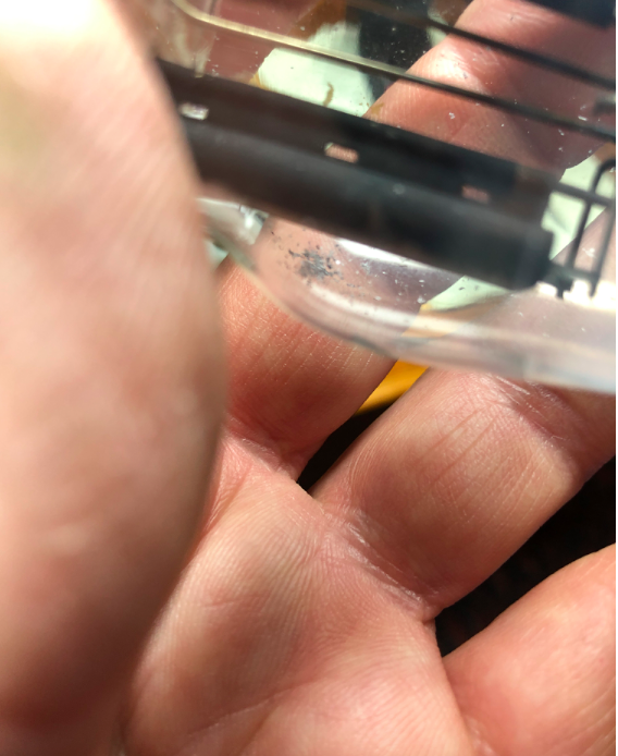
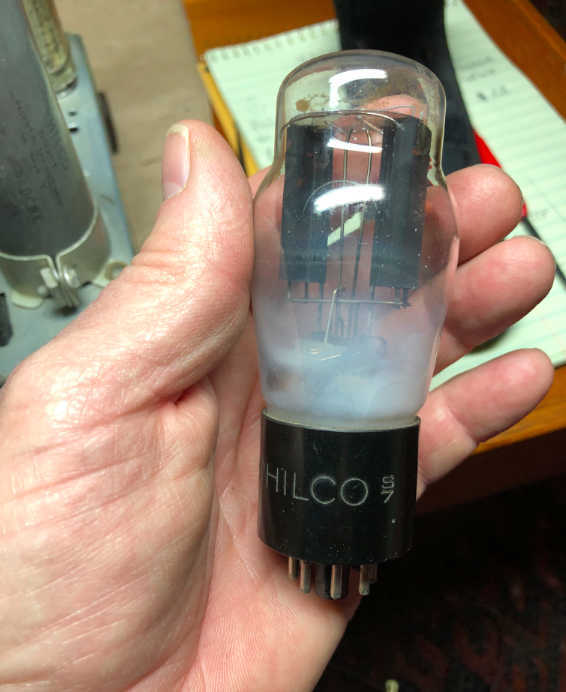
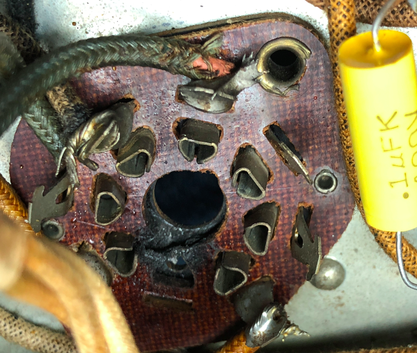
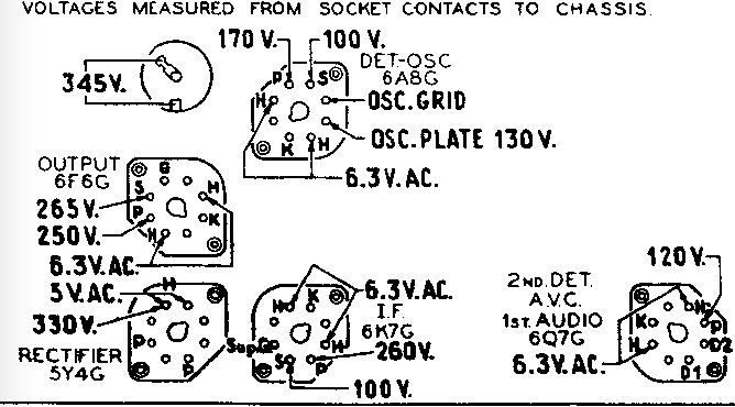
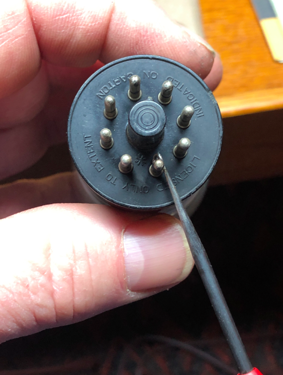
I am getting near the end of my 38-10 re-cap and repair, and noticed a charred receptacle at one pin location on the rectifier tube (5Y4G) socket. Being a rank beginner and knowing nothing about these tubes, I'm looking for information on 1) whether all 8 pins on the tube are used, and 2) if this foggy tube is an indication of a short or bad tube? I'm attaching the tube schematic and a photo of the charred pin position and corresponding pin, marked with my tool. Thanks for your help.
                   
#2

Hello, The tube looks like it went to air >lost vacuum< yes it would be bad. The tube socket will need to be replaced. It uses a 8 pin octal socket.
4 of the pins are used on the rectifier tube. Pins 3&5 are the plates and 7&8 are the filaments.
#3

Time for a new socket. It's burnt where there is hv ac. Would replace w/a molded one rather than the cheap wafer job. Not sure abt the tube the cloudiness maybe an issue. To be on the safe side wouldn't hurt to replace.

When my pals were reading comic books
I was down in the basement in my dad's
workshop. Perusing his Sam's Photofoacts
Vol 1-50 admiring the old set and trying to
figure out what all those squiggly meant.
Circa 1966
Now I think I've got!

Terry
#4

Yep, the getter be gone on that tube (silver at bottom) ... Time for a replacement, as well as the socket..

Steve


Attached Files Image(s)
   
#5

Ok, thanks all for the input! Now to find a socket....
#6

Be sure to specify the mounting screw hole spacing. The wrong socket may require drilling, not cool...

Stay away from China sockets if you can, rumor control has it the tension on the pins is rather weak... Or YMMV...

Test the power transformer before going too far. Tape up the filament and high voltage leads, be sure there is no shorts in the rest of the filament circuits. Power the chassis and wait for 1/2 hour. If no crackling noises followed by smoke and heating after half an hour the transformer is O.K. Icon_smile

Chas

Pliny the younger
“nihil novum nihil varium nihil quod non semel spectasse sufficiat”


Users browsing this thread: 1 Guest(s)
[-]
Recent Posts
Electrolytic restuffing/internals
I don’t have a vise so I had to hold it in my hand. Not optimal but covered up by the hvac tape in the end. I have a few...bridkarl — 11:52 PM
Electrolytic restuffing/internals
Bridkarl A question. For a hacksaw the cut looks a little...jagged. Why?morzh — 11:45 PM
The list of my radio & TV collection!
As usual, an interesting post from you, Peter. This seems to be similar to the RCA 3-BX-671 and the Zenith Transoceanic...MrFixr55 — 11:41 PM
The list of my radio & TV collection!
Hello Peter, Thank you for sharing your new video and looks like your weather is nice their too. it was like 25 Cel...radiorich — 11:05 PM
Electrolytic restuffing/internals
hello bridkarl, I will post some better photos ! Sincerely Richardradiorich — 10:14 PM
Electrolytic restuffing/internals
I just taped the two pieces of the cap together, but I can see your method is better. I just held the lead in with solde...bridkarl — 08:18 PM
Electrolytic restuffing/internals
hello bridkarl, Well done ! Here is a Photo of the base of Philco capacitor that I cut open you can see how I glued th...radiorich — 08:14 PM
philco predicta
Hi CGL18, Here is a link for the schematic from the Early television Foundation: WARNING!! One side of the Chassis i...MrFixr55 — 08:09 PM
The list of my radio & TV collection!
Peter; I like Canadian General Electric sets, whilst the model numbers are often the same as their U.S General Electr...Arran — 05:44 PM
Electrolytic restuffing/internals
Did as suggested. Cut can with hacksaw, removed internals, attached new 8mf cap - with ample use of cardboard and elec...bridkarl — 03:36 PM

[-]
Who's Online
There are currently no members online.

>