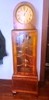
Maas-Rowe Carillon Amplifier
Posts: 1,222
Threads: 50
Joined: Oct 2017
City: Allendale, MI
I'm not sure how to calculate the best value for the inductor in a pi filter arrangement. Not sure that the .05 has a lot to do with it but I'm not fully knowledgeable in these things. I think it easiest to just measure it! I will do that for you.
Posts: 1,222
Threads: 50
Joined: Oct 2017
City: Allendale, MI
I tried to measure the choke. It has a DC resistance of 1850 ohms. My inductance meter goes up to 20 Henry but it would not measure it. So I assume it is over that.
Posts: 5
Threads: 0
Joined: Jun 2020
City: Strongsville
State, Province, Country: OH
What voltages are you getting?
Looks like a 380RMS PT and a 3.6k OT
Posts: 1,620
Threads: 53
Joined: Nov 2017
City: Menlo Park
State, Province, Country: CA
Could you put a decent sized capacitor across the choke and look at the resonant frequency that results from the LC circuit? If I've calculated correctl, for example, 1 uF should yield about 35 Hz, for a perfect choke of 20H.
Just a thought...
I don't hold with furniture that talks.
Posts: 5
Threads: 0
Joined: Jun 2020
City: Strongsville
State, Province, Country: OH
My meter only goes up to 20H as well and I have no reading. I'll have to pull out the oscilloscope
Posts: 18,427
Threads: 622
Joined: Oct 2011
City: Jackson
State, Province, Country: NJ
I doubt you need to know the exact value of the inductor.
Suffices it to know, it is big and in 10s of H.
0.05uF cap is there to try to compensate for the ripple voltage.
The idea is, I think, that if there is a ripple via the inductance, and the current lags the voltage by 90 degrees, then that ripple could be nullified by parallelling a capacitor that would provide the same size ripple current which leads the same voltage by 90 degrees. The resulting phase shift between the AC component of the currents (ripple current via inductance and the current via the cap) is 180 degrees.
Of course the shape of the current through the inductor is not exactly the same as it is via the cap. So they will not totally compensate each other.
Picking the cap depends on the load. With the load current of a certain size the ripple voltage is Iripple*Rload.
You could watch this on a scope.
Then knowing the voltage you could keep inserting the caps until you see the optimal reduiction.
Or if you want to be a bit more scientific and calculating, measure both load current and the load voltage, calculate the impedance, and solve for the capacirtive impedance so the divider between the cap and the load gives you the same amplitude of the voltage as the ripple AC component given the AC ripple before the choke.
I would do the former as it is easy enough.
People who do not drink, do not smoke, do not eat red meat will one day feel really stupid lying there and dying from nothing.
Posts: 1,222
Threads: 50
Joined: Oct 2017
City: Allendale, MI
I didn't check voltages while I had the bottom cover off. If you get a similar DC reading you probably can assume the choke is ok. Is that what you are trying to determine? My amp runs pretty much hum free. with the caps I put in it (about the same as original.)
(This post was last modified: 06-08-2020, 09:02 PM by rfeenstra.)
Posts: 5
Threads: 0
Joined: Jun 2020
City: Strongsville
State, Province, Country: OH
I was curious about plate voltages, not necessarily in regards to the choke.
Posts: 1,222
Threads: 50
Joined: Oct 2017
City: Allendale, MI
On which tubes? It'll be a while before I can take it apart again.
Posts: 374
Threads: 41
Joined: Dec 2019
City: Elkhart
State, Province, Country: Indiana
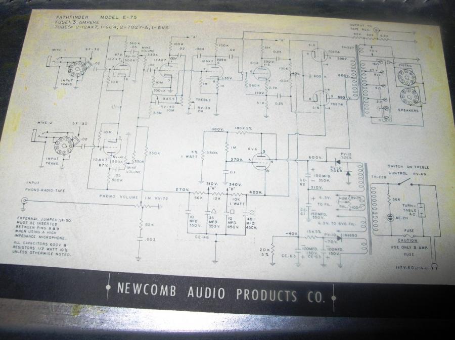
I unfortunately do not have the service manual, or schematic for the Newcomb Pathfinder Amp, as that was in the original owners manual that came with that unit and that unfortunately went with the unit to the current owner of the unit when I sold it to him a couple of years ago.
I do think maybe I could look it up in Riders or Beitmans or perhaps it was covered in Sam's?
EDIT:
I found the Schematic I had from the Newcomb Amplifier I had, it was on another audio forum I used to frequent.
See the picture below.
Posts: 1,222
Threads: 50
Joined: Oct 2017
City: Allendale, MI
Posts: 5
Threads: 0
Joined: Jun 2020
City: Strongsville
State, Province, Country: OH
That is really high voltage for 6L6
Posts: 7,323
Threads: 270
Joined: Dec 2009
City: Roslyn Pa
7027A's they have a little higher ratings than the 6L6G's.
Better pray the bias supply doesn't give up or you can
kiss the opt goodby.
When my pals were reading comic books
I was down in the basement in my dad's
workshop. Perusing his Sam's Photofoacts
Vol 1-50 admiring the old set and trying to
figure out what all those squiggly meant.
Circa 1966
Now I think I've got it!
Terry
(This post was last modified: 06-24-2020, 02:07 PM by Radioroslyn.)
Posts: 1,222
Threads: 50
Joined: Oct 2017
City: Allendale, MI
I measured some of the voltages on my amp. Output from the rectifier is just over 400 and that feeds the center tap of the OT. The screens are at 295. I couldn't measure the plates as the amp goes into convulsions when I put the meter on the plates! The self bias is as 22 volts.
Posts: 18,427
Threads: 622
Joined: Oct 2011
City: Jackson
State, Province, Country: NJ
Do you have a modern meter or an old type?
People who do not drink, do not smoke, do not eat red meat will one day feel really stupid lying there and dying from nothing.
Users browsing this thread: 2 Guest(s)
|
|
Recent Posts
|
|
Plug Voltages Needed For A 1943 CRV-20130 Power Supply
|
| That looks a lot like an aircraft connector of some kind, even if it's a U.S.N power supply. I have a book somewhere abo...Arran — 02:56 AM |
|
Plug Voltages Needed For A 1943 CRV-20130 Power Supply
|
| hello david,
I have a similar generator in my collection that features a cast iron, single-cylinder Briggs & Stratt...radiorich — 01:00 AM |
|
under chassis parts locator diagram for 1938 Zenith 9s262
|
| Has anyone gone to the trouble of creating an under chassis parts locator image? Yes, I can identify components by foll...bobloney — 08:57 PM |
|
Plug Voltages Needed For A 1943 CRV-20130 Power Supply
|
| Try looking at this site the book mark is for a old generator that I was given. David https://radionerds.com/index.ph...David — 08:36 PM |
|
Plug Voltages Needed For A 1943 CRV-20130 Power Supply
|
| Hello Everyone,
I am looking for voltage identification for all the pin positions on the socket of a CRV-20130 power su...Tonym4704 — 08:16 PM |
|
Philco P45-6365 Universal Transformer Instruction Manual
|
| Can anyone guide me to where this may be found?GRG — 03:00 PM |
|
54C Complete Teardown/Rebuild
|
| I don't think that I have encountered a 12Z3 before, curious how it uses one of those but includes a #43, which is a 25 ...Arran — 02:17 PM |
|
HiFi (Chifi) tube amp build - but my own design.
|
| It's the other forum. I'm also in DIY, but mostly read there. Honestly, I kinda jumped into this without much thought to...TV MAN — 10:43 AM |
|
Philco 71 Code 125
|
| Hello,
I am in need of a schematic for this radio. Mine has the three separate circular tube shields and a shadow me...dconant — 08:06 AM |
|
Stromberg Carlson 1500 Squeal
|
| And life just keeps getting more complicated.dconant — 07:57 AM |
|
Who's Online
|
There are currently 1698 online users. [Complete List]
» 1 Member(s) | 1697 Guest(s)
|
|
|

|
 
|