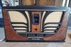
Hello all , New to the forum and starting a 47-1230 restoration. The radio was my parents first piece of furniture they bought when he came back from the war (WWII). I have had it for 30 years or so and it was working until 10 years ago. Then the power transformer caught on fire, I put it out immediately with no other damage. Now I have the time and decided to try to get it working again. I ordered the replacement transformers and getting prepared to start. But trying to plan my strategy to approach this project. I don't want to dive in to deep and get in over my head, so:
1st. Do I need variac?
2nd Should I replace the paper /wax caps before applying any power or just replace the power transformer and see what happens.
Im thinking the latter then replace the caps systematically. Any help or advise would be welcome.
The reason for the failure of the original power transformer should be investigated before applying power to the set again, it's very unusual for a Philco to suffer from a transformer failure for no reason. I would check for resistance between the B+ liine and chassis, as well as the tube filament wiring, including the pilot lamp sockets. More then likely it was a failed input filter capacitor, but you never know.
Regards
Arran
Yes god points, flaming wax was dripping from the transformer, I assumed the transformer broke down internally but maybe touch much current draw from something else. B+ on secondary?
Like Arran said more than likely the input cap in the power supply shorted took out the the 5Y3 and the HV winding on the power transformer rendering it scrap.
Should I replace the paper /wax caps before applying any power
Good idea!
just replace the power transformer and see what happens.
Bad idea stock up on fire insurance.
Im thinking the latter then replace the caps systematically. Any help or advise would be welcome.
I would do it all at once.
When my pals were reading comic books
I was down in the basement in my dad's
workshop. Perusing his Sam's Photofoacts
Vol 1-50 admiring the old set and trying to
figure out what all those squiggly meant.
Circa 1966
Now I think I've got it!
Terry
(This post was last modified: 01-23-2021, 11:06 PM by Radioroslyn.)
I just had a look at the Nostalgia Air documentation. Generally, paper caps are identified visually and by value. Paper caps are usually tubular and have a black stripe on one end called the "outside foil". Values can be as low as .001mf (microfarads). You can buy the plastic film caps at 630 volts either from several sources here on the Forum or online from Mouser Electronics and others. When buying replacements for the electrolytics buy the 105° Japanese aluminum ones from Nichicon and others, or Illinois Capacitor. Modern capacitance values are slightly different from the originals, eg. .047mf vs .05mf. These will be sufficient replacements as the originals have a 20% tolerance.
When replacing any condensers, always use new ones of AT LEAST the same voltage rating or higher. Higher is better. Use condensers of the same capacitance or as close as you can get. In power filtering circuits it is OK to go up to 1 1/2 times the original capacitance. Oh, by the way, I still call condensers by the old name, since I have been working with electronics since that was still the accepted term, although "capacitor", what most folks call them now, was beginning to be used. Yes, I am that old.
So I am finally removing the power transformer and slowly id ing all the wires and trying to correlate to the new one. Radiodaze sent me two separate transformers because there isn't one with HV ,FIL1 ,FIL2 and rectifier. the little xmfer is 6.4 v @.0.6A for the audio tubes , not sure which ones are the audio tubes???
When my pals were reading comic books
I was down in the basement in my dad's
workshop. Perusing his Sam's Photofoacts
Vol 1-50 admiring the old set and trying to
figure out what all those squiggly meant.
Circa 1966
Now I think I've got it!
When my pals were reading comic books
I was down in the basement in my dad's
workshop. Perusing his Sam's Photofoacts
Vol 1-50 admiring the old set and trying to
figure out what all those squiggly meant.
Circa 1966
Now I think I've got it!
Terry
(This post was last modified: 01-31-2021, 12:42 AM by Radioroslyn.)
Have no idea. Philco uses a non standard color code on their transformers so your on your own.
When my pals were reading comic books
I was down in the basement in my dad's
workshop. Perusing his Sam's Photofoacts
Vol 1-50 admiring the old set and trying to
figure out what all those squiggly meant.
Circa 1966
Now I think I've got it!