Posts: 16,577
Threads: 574
Joined: Oct 2011
City: Jackson
State, Province, Country: NJ
Gary,
Yes, that's what I meant by mentioning that automotive spray.
Mr.Fixer
Thanks for the link.
Ron,
This bucket of popcorn ain't big enough 
People who do not drink, do not smoke, do not eat red meat will one day feel really stupid lying there and dying from nothing.
Posts: 4,946
Threads: 54
Joined: Sep 2008
City: Sandwick, BC, CA
Believe it or not the Canadian G.E sets were more then likely made by G.E with imported tooling, Canadian Westinghouse did the same. Canadian Westinghouse had a version of a Columnaire called a model 801, the circuit is very similar to the Victor and C.G.E sets like the S-22, but the chassis layout is different in that it has sockets for the three directly heated tubes on the side apron, the chassis is mounted sideways with the two #45s and the #80 pointing straight up. I believe that the Canadian Westinghouse 801 Columnaire is a 1931-32 model, they had a more conventional version as well, mounted in a tombstone cabinet, I have the service folder for that, I kind of wish that C.G.E and Victor sets were built the same way rather then that deep, layered chassis copied from the U.S sets.
Regards
Arran
Posts: 16,577
Threads: 574
Joined: Oct 2011
City: Jackson
State, Province, Country: NJ
Oh gee.....this is an inconvenient radio to deal with, to put it mildly. I thought the AK82 was, but no, it is nervously smoking, having stepped aside and yielded the pedestal to the RCA.
First I noticed that a regulator was practically frozen. Judging from it having the power switch, I thought first it was the volume pot, but then realized it was the tone control. I desoldered it and took it out. My first thought was to inject some Fader Lube deoxit, using my Trolmaster, but then I thought that would not be a good idea without clear understanding what was inside.
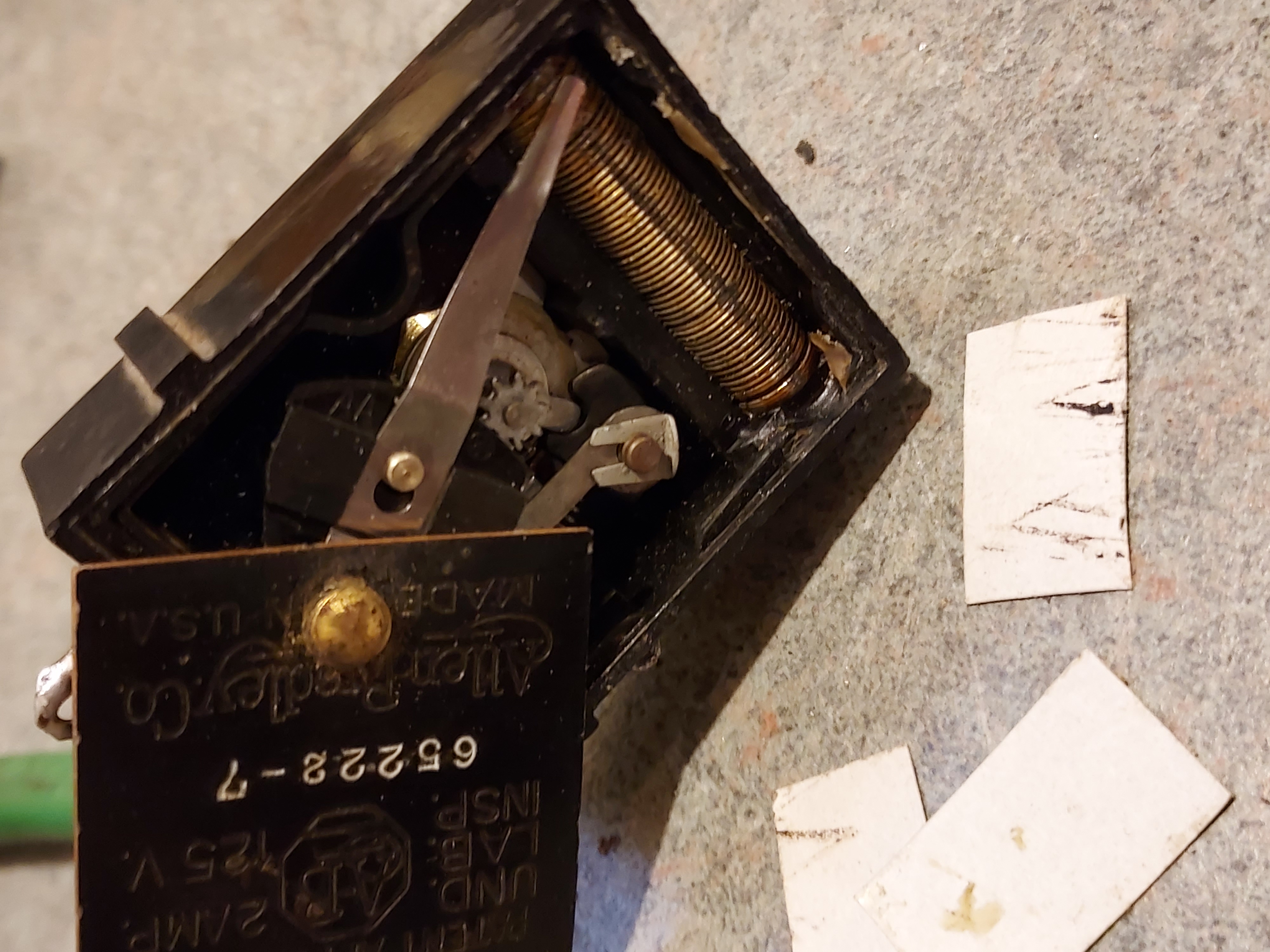
The cover of the pot is held by one rivet. Som in order to open it, I put small pieces of fishpaper in each corner, so they would guide the corners of the cover past the box' walls, and rotated the cover around the rivet.

You could see the rotating gear and the rheostat; the switch is obscured by the cover, but accessible.
First I put some silicon lube right to the shaft (where the sprocket is visible) and worked it for 10-20 seconds with pliers; it quickly unfroze and after 20 seconds it was easily, without much resistance, rotating with fingers.
Then I used swabs soaked in alcohol to clean the switch contacts and applied a little dab of D5 contact cleaner. Then I cleaned the rheostat with alcohopl (surprisingly clean) and applied a dab of F5 Fader lube to it.
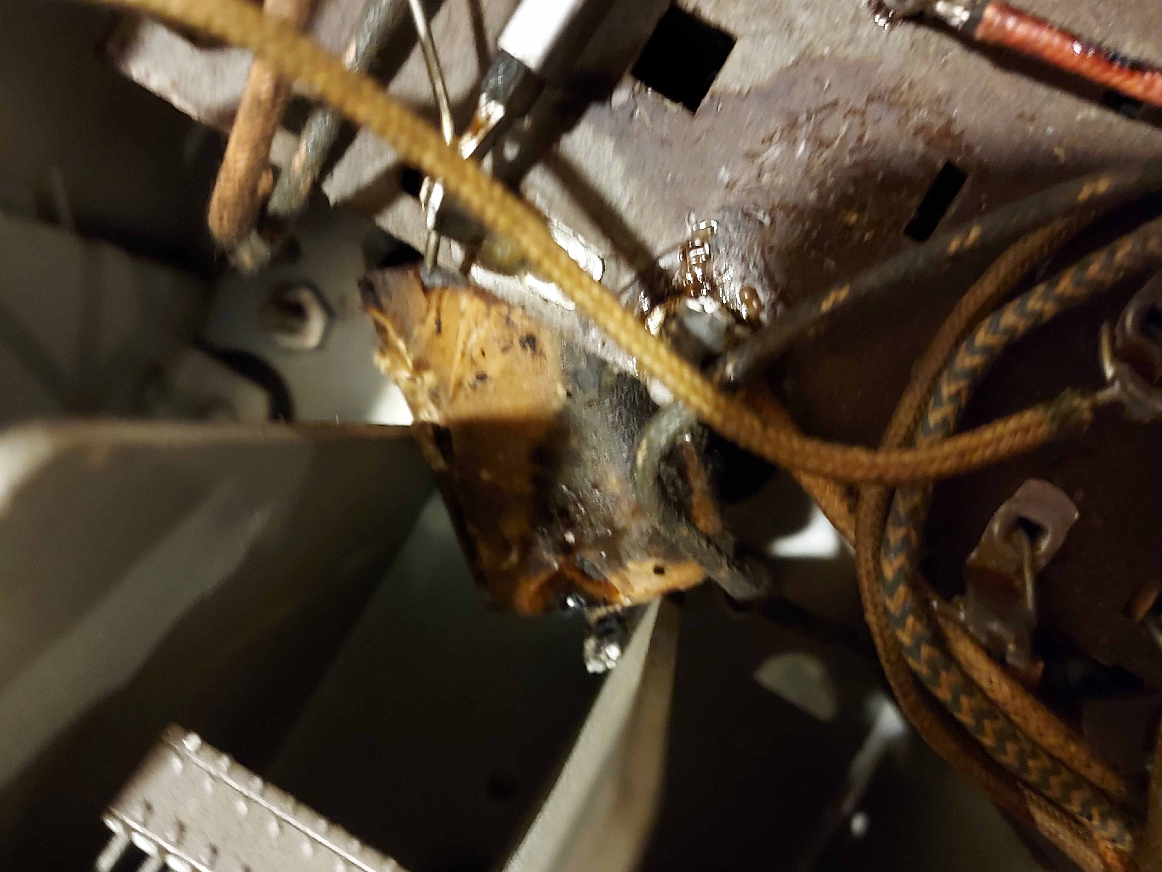
Then I decided to take on the Resistor Board. The first cap, C26, seems to be a mica, juding by the value and by the fact that the capacitance is right on the money. Then of course came the C24, 0.2uF. This thing is on the bottom side. Behind a tangled web of wires. Having the flat tape type leads. So cannot be cut out. After some thinking, using Russian analogs of 4-letter vocabulary and rotating the chassis around several times, I was able to drop it inside.

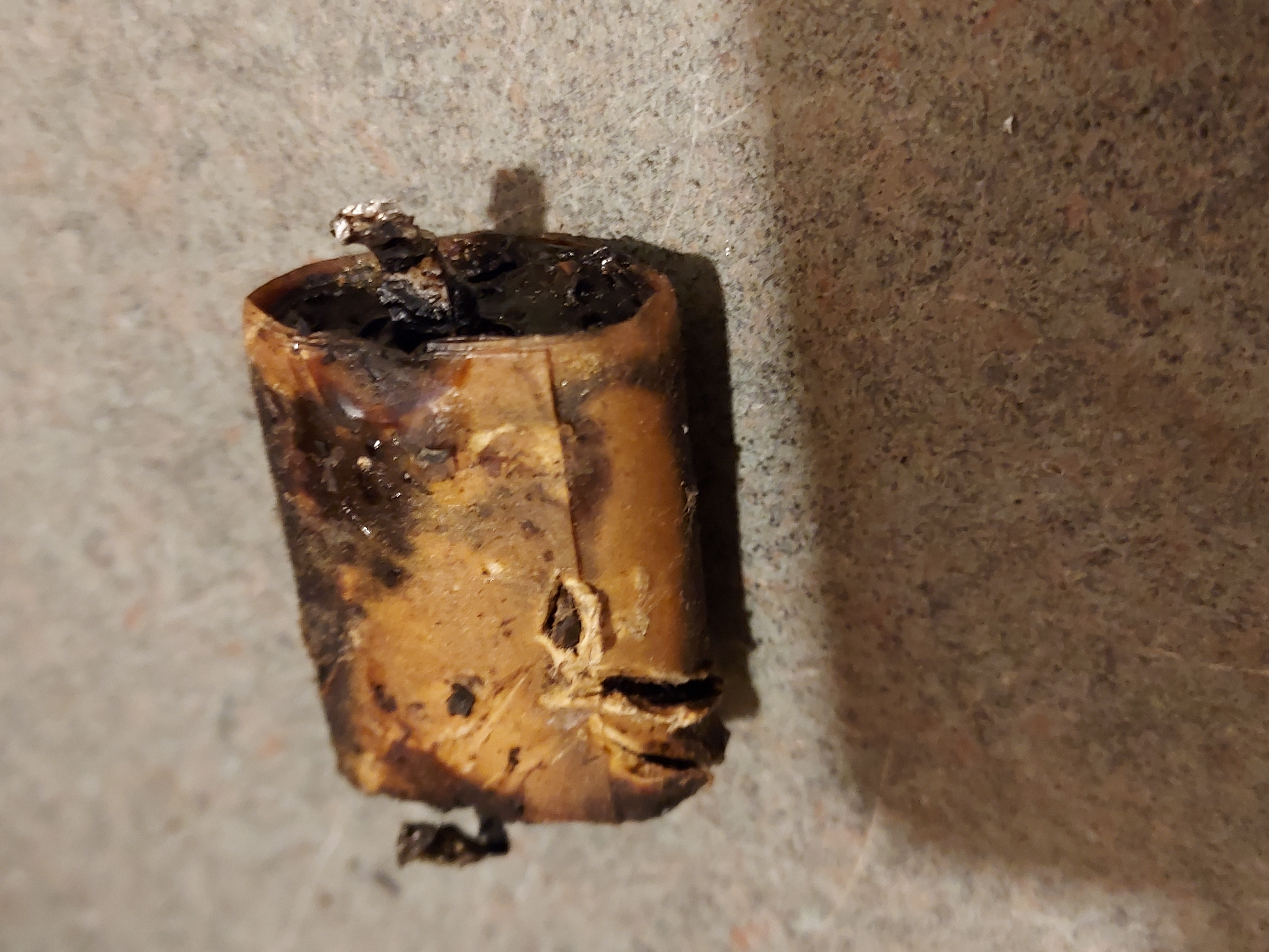
Here it is, out of the chassis. An ugly, ugly creature. I wouldn't even think of restuffing it - it is a piece of tar wrapped in paper.

Then I was able to put a new cap inside. Not without using gravity, bending the leads in some intricate ways to guide them to the through rivets they are soldering to, but I was successful.
Oh....and the large inductance, L11, on the same board seems to be open. That's a bummer - this is listed with resistance value instead of inductance, and it is 3K which means a lot of very thin wire.
After this I felt exausted and in need of some beer in my cardiovascular system, which made me stop, then sit down to write this report, and now I am about to move to the beer part.
Cheers!
People who do not drink, do not smoke, do not eat red meat will one day feel really stupid lying there and dying from nothing.
Posts: 2,197
Threads: 159
Joined: Jan 2013
City: Westland, MI
Mike!?!? You use colorful Russian language? Nyet!!! Take care and BE HEALTHY! Gary
"Don't pity the dead, pity the living, above all, those living without love."
Professor Albus Dumbledore
Gary - Westland Michigan
Posts: 16,577
Threads: 574
Joined: Oct 2011
City: Jackson
State, Province, Country: NJ
Gary,
Yes, and it is a great tool! Everyone knows that a Russian can accomplish just about anything using a sledge hammer and some "mother". It is an integral part of every technical accomplishemnt in Russia, especially when it comes to fixing things.
Remember the Russian cosmonaut guy in "Armageddon"? Fixing a panel with blows? I wonder why they did not show the language he simply had to use while doing that.
People who do not drink, do not smoke, do not eat red meat will one day feel really stupid lying there and dying from nothing.
Posts: 1,288
Threads: 11
Joined: Jul 2020
City: Greenlawn
State, Province, Country: NY
That scene from Armageddon was hysterical!
One of the labs that I serviced had a Soviet Refugee staff. Great folks, they loved this country, and I enjoyed their sick sense of humor (even the women were a little twisted). I was taught a phrase or two that would get me banned from the Phorum if I went any further. Maybe the Cosmonaut in Armageddon used it.
"Do Justly, love Mercy and walk humbly with your God"- Micah 6:8
"Let us begin to do good"- St. Francis
Best Regards,
MrFixr55
Posts: 1,288
Threads: 11
Joined: Jul 2020
City: Greenlawn
State, Province, Country: NY
This circuit looks more and more interesting. Lots of resistance in the cathode circuit of the Det / 1st AF tube (Diode biased?)
L11 appears to be an RF choke in series with the connection between the driver transformer primary and the cathode of the Det /1st AF. Wonder if it is really necessary and if you can just "try in" a 3K resistor. If it oscillates or sounds too harsh, then you have to worry about making the choke.
"Do Justly, love Mercy and walk humbly with your God"- Micah 6:8
"Let us begin to do good"- St. Francis
Best Regards,
MrFixr55
Posts: 4,946
Threads: 54
Joined: Sep 2008
City: Sandwick, BC, CA
Mike;
When I was repairing that G.E J-82 I removed the resistor board altogether, after making a diagram, replaced the questionable components, then re-installed it. I basically treated the board like a large terminal strip, but compared to my Rogers 10-60 it was easy, they at least used terminals to connect the components, the Rogers used some odd resistors with ends like terminals to make all the connections.
Regards
Arran
Posts: 16,577
Threads: 574
Joined: Oct 2011
City: Jackson
State, Province, Country: NJ
Arran
Well, it does not present problems with the resistors change. Taking the board off though would requiere drilling out the rivets: it does not use bolts and nuts, just rivets.
Mr. Fixer
Worse yet, L12 is open too. And the antenna primary coil.
And Gosh knows what else.
This radio might just prove to be a nightmare.
People who do not drink, do not smoke, do not eat red meat will one day feel really stupid lying there and dying from nothing.
Posts: 1,288
Threads: 11
Joined: Jul 2020
City: Greenlawn
State, Province, Country: NY
That's a shame. Is the interstage transformer open? Dang, this is starting to sound like a Philco with bad RF, Osc transformers! U may want to ohm out the rest of it. Shame, the thing does look clean. Wonder if it took a lightning hit?
Did U get the Cap Pack rebuilt?
You may be able to get away with subbing a resistor for R12 and connect a long wire to the RF Amp Grid cap so U can fire it up and find out what else U need.
"Do Justly, love Mercy and walk humbly with your God"- Micah 6:8
"Let us begin to do good"- St. Francis
Best Regards,
MrFixr55
Posts: 1,941
Threads: 129
Joined: May 2008
City: Omak
State, Province, Country: WA
Hello morzh,
Hopefully that transformer can be fixed !
Sincerely Richard
Posts: 16,577
Threads: 574
Joined: Oct 2011
City: Jackson
State, Province, Country: NJ
MrFixr
Well, I have not looked at it yet. Honestly, this specific RCA is not my bucket list radio, so if too many things are open, I might just give up on it, as the expense will be to great.
And I cannot find the inductances of both chokes: they are both listed in Ohms, 3,000 Ohm each. i of course could possibly try to get to the wire and measure it on my LCR meter but this is only if the wire is intact. Another thing to try - counting turns. I hate it.
The antenna coil has flat disk type winding. Grrrr.....
People who do not drink, do not smoke, do not eat red meat will one day feel really stupid lying there and dying from nothing.
Posts: 4,946
Threads: 54
Joined: Sep 2008
City: Sandwick, BC, CA
Mike;
I seem to recall taking the resistor board out of the J-82, so either the American made RCA sets are made differently then the Canadian G.E/Victor models, or the board is held in by some machine screws holding the mounting brackets onto the chassis rather then screws holding the board itself in. It was over 20 years ago that I worked on a J-82, but I do remember moving a comparable board, somehow.
Regards
Arran
Posts: 1,288
Threads: 11
Joined: Jul 2020
City: Greenlawn
State, Province, Country: NY
I am wondering if you can't just replace the chokes with just plain resistors. RCA used these a lot in earlier biased "power detectors" but have not used them in later radios, especially those using diode detectors. These RFCs are in the plate and coupling circuits from the 1st AF Amp to the interstage transformer. Iam pretty sure that the output stage is Class A Push Pull. If the secondary of the antenna transformer is good, just connect a long wire antenna to the grid cap of the 1st RF Amp, at least to test the radio. I won't bet my life on it but will bet lunch off the (non-existent) McD's $1.00 menu that the radio will work in that manner if nothing else is wrong.
Below is a section of the R75A schematic showing differences in the detector and audio section.
[attachment=28025]
Note that L12 is not in this circuit. The detector circuit has been rearranged from diode biased 1st AF Amp to a much more standard AF Circuit with a more standard volume control. This will also allow you to input an external audio signal. You will likely need to keep the original volume control circuit as it works by adjusting the bias on several circuits, in conjunction with AVC. in later radios with single end AF Output and RC Coupling between the 1st AF and Output, there is no RF Chocke in the audio circuit. This is my rationale for suggesting replacing L11 and L12 with resistors and seeing what happens. The fact that the output tubes are 2A5s and not 47s does not really have a bearing on this issue. In fact, 47s can be replaced by 2A5s without much modification other than the tube socket, wiring in the cathode at the center tap and possibly the cathode bias resistor.
"Do Justly, love Mercy and walk humbly with your God"- Micah 6:8
"Let us begin to do good"- St. Francis
Best Regards,
MrFixr55
Posts: 16,577
Threads: 574
Joined: Oct 2011
City: Jackson
State, Province, Country: NJ
I also think the L11 and L12, if teplaced by 3K resistors, will not stop the output from working.
More to it, I am not suire many would notice.
Then again, some characteristics will change: RCA was know for trying to improve the sound and gthese might be the tweaks to do exactly that. How much that was effective, I would not know.
Simulation might reveal the transfer function, to see what part if any of the sound it would affect and how it would make the broadcast (standard bandwidth) music sound.
People who do not drink, do not smoke, do not eat red meat will one day feel really stupid lying there and dying from nothing.
Users browsing this thread: 1 Guest(s)
|
|
Recent Posts
|
|
Philco 42-345 Restoration/Repair
|
| RodB
:beerchug:Vlad95 — 10:22 AM |
|
Philco 42-345 Restoration/Repair
|
| Vlad, you nailed it. Swiss and German roots.RodB — 09:54 AM |
|
5U4 vs 5Z4 tubes
|
| Well this is a Hallicrafters SX/9 circa 1936.
No real issues so far although I dodged a real bullet with a cap that was...bridkarl — 07:59 AM |
|
5U4 vs 5Z4 tubes
|
| The pinout is the same but the 5U4 has a 3 amp filament, verses 2 amps or less on the 5Z4. I think that the pinout of a ...Arran — 12:04 AM |
|
Philco 42-345 Restoration/Repair
|
| By the way.
osanders0311
Take a look here: Dial cord stringing Guides
May be here you can fount correct string settin...Vlad95 — 11:15 PM |
|
5U4 vs 5Z4 tubes
|
| 5U4 and 5Z4 almost identical. I think nothing happened if you left 5U4 instedad 5Z4 long time.
Just heater current 5U4 ...Vlad95 — 11:02 PM |
|
Philco 42-345 Restoration/Repair
|
| Hello Vlad95 ,
Very Funny !
Sincerely Richardradiorich — 11:01 PM |
|
Philco 42-345 Restoration/Repair
|
| RodB
You are European yourself :evil:
I'm Canadian for the last 30 years :snowman:
But not Yankee :lol: Vlad95 — 10:49 PM |
|
Philco 42-345 Restoration/Repair
|
| The band switch selects different oscillator coils for the band selected. I would look for a bad connection in the switc...RodB — 10:31 PM |
|
Philco 42-345 Restoration/Repair
|
| Hang in there...PaulPaul Philco322 — 09:30 PM |
|
Who's Online
|
There are currently 1249 online users. [Complete List]
» 2 Member(s) | 1247 Guest(s)
|
|
|

|
 
|


![[-] [-]](https://philcoradio.com/phorum/images/bootbb/collapse.png)


