Welcome Guest! Be sure you know and follow the Phorum Rules before posting. Thank you and Enjoy! (January 12) x

Thread Rating:
  • 0 Vote(s) - 0 Average
  • 1
  • 2
  • 3
  • 4
  • 5

TDS320 scope
#1

Well, it is not a necessity. I was given it from my work; they did not know what to do with it.
I though at the time, it was working.
When I turned it on, the traces were there but the Front Panel buttons and controls did not work.
After many power-ups it would work, then would cease to work....after warm-up it could work for a long time and I wouldn't be able to stop it from working to troubleshoot.

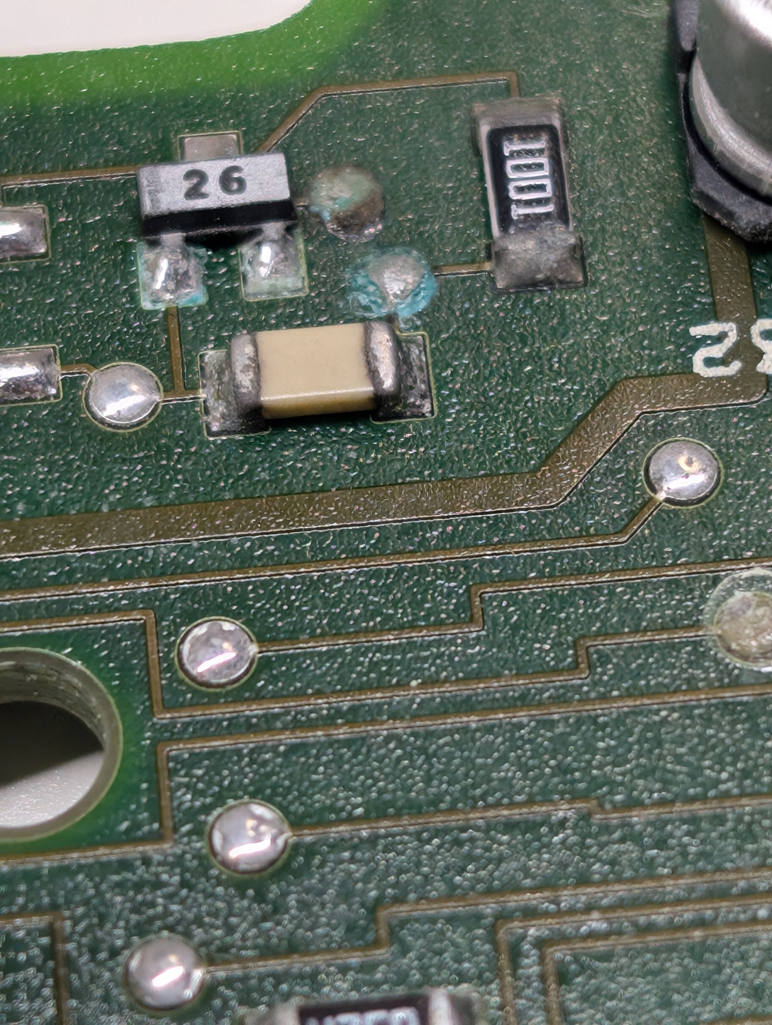
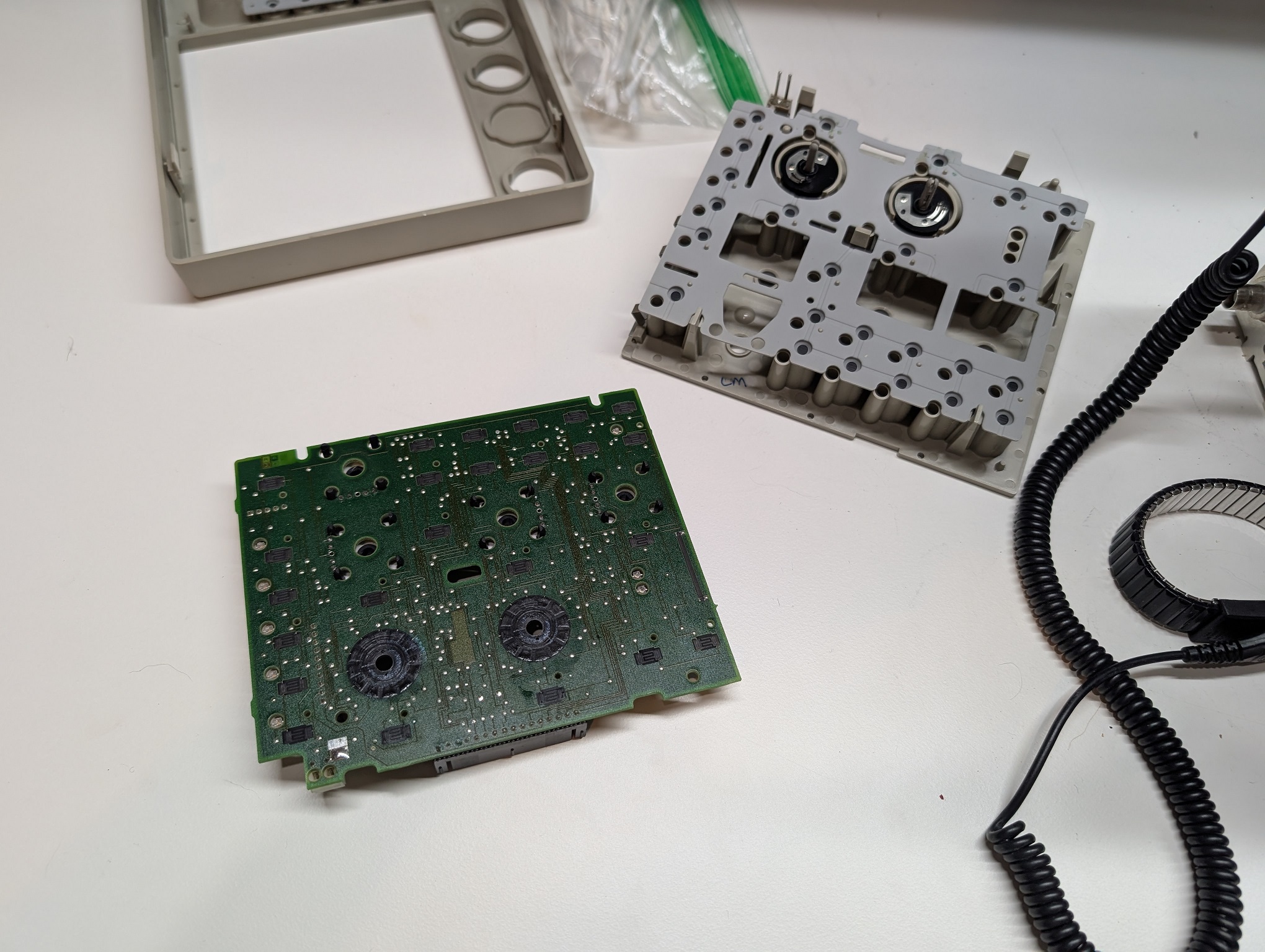
The troubleshooting diagram points to the main board (Main CPU plus the front end). But when I took a closer look at the Front Panel unit, I noticed this:
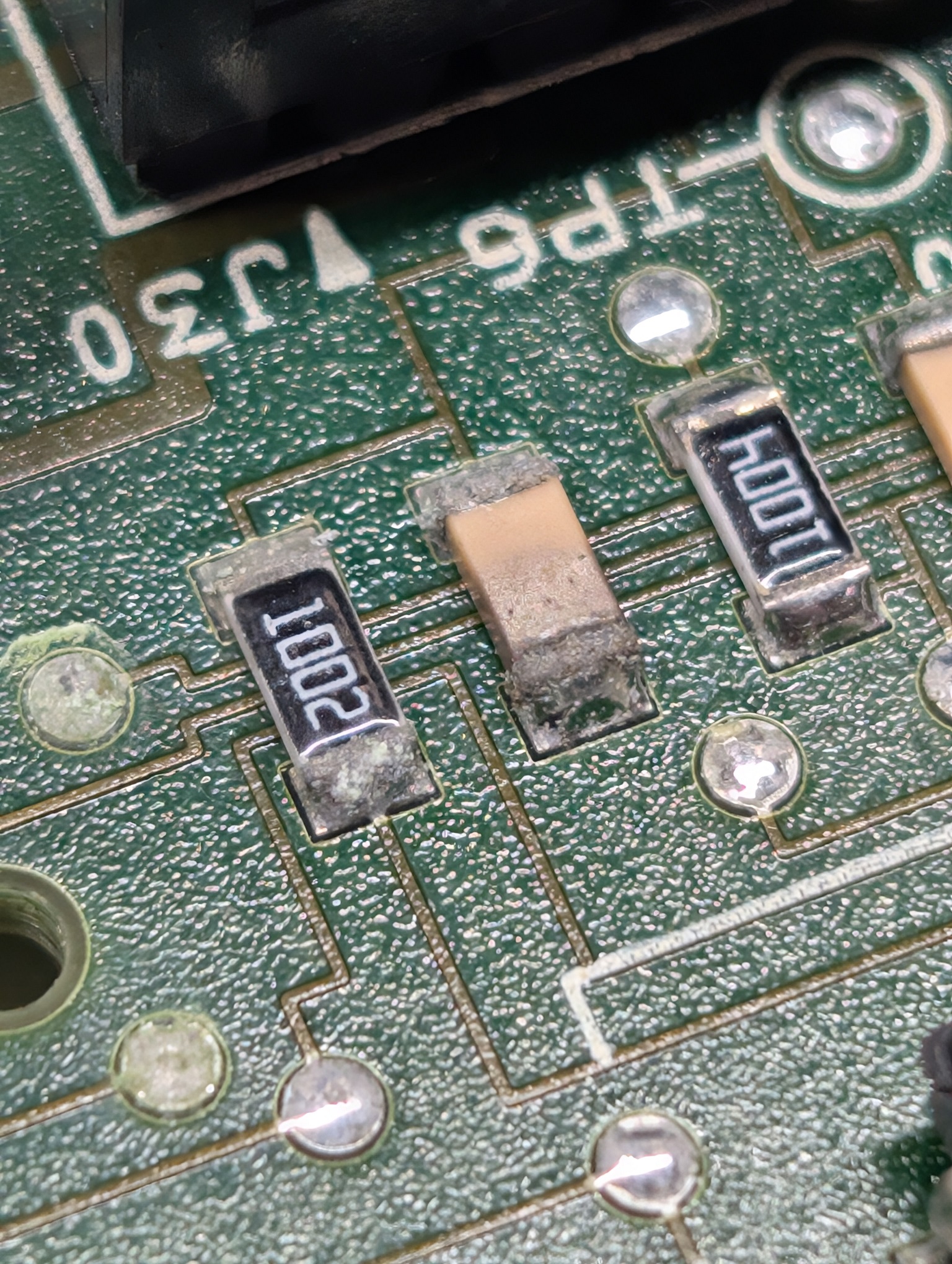
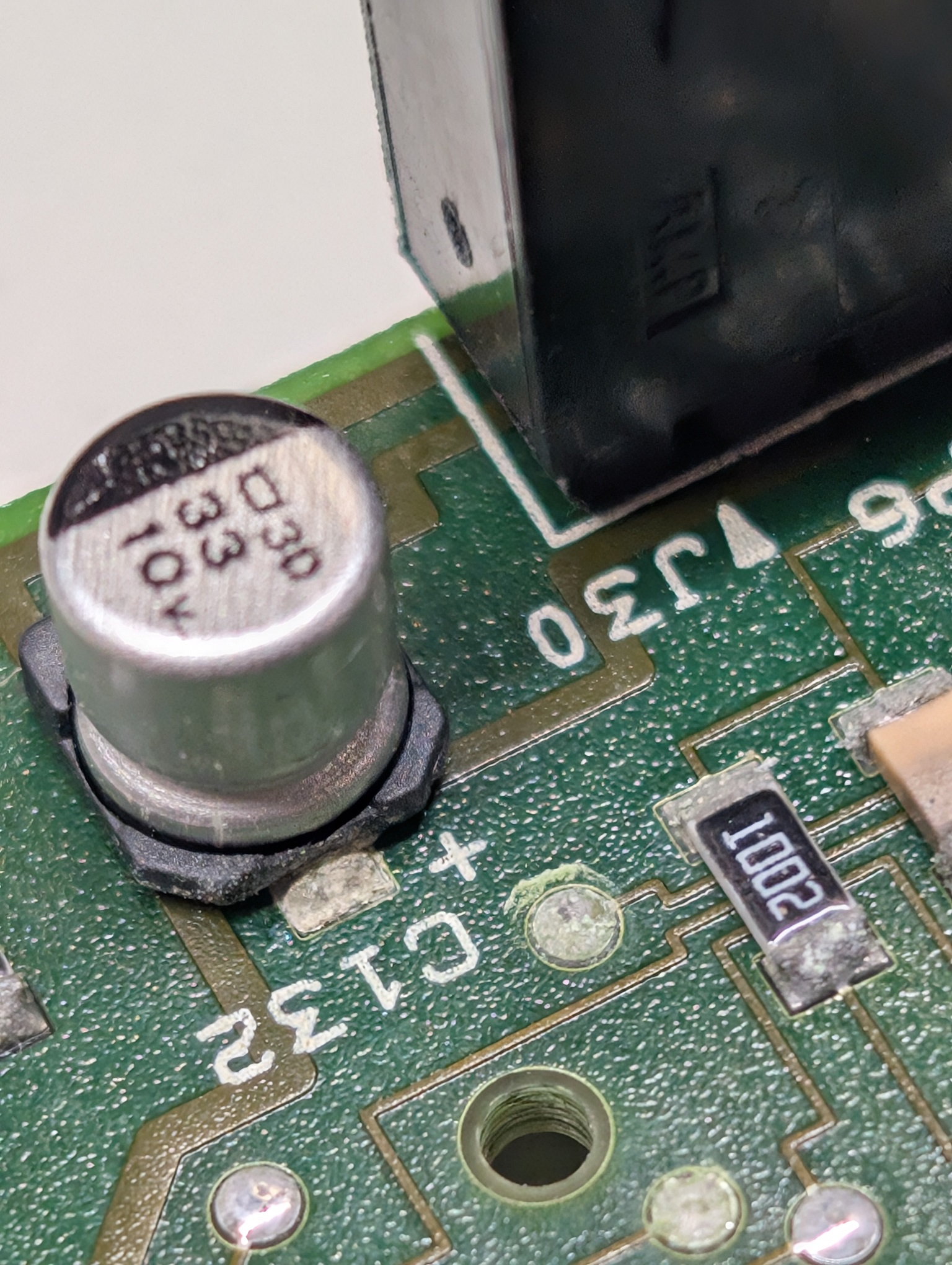


Also some oxidation in the connector that I have touched up.

Some of it are electrolytic caps, that I will need the solder tweezers to lift up, and I only have them at work, and I am back to work on 10th.
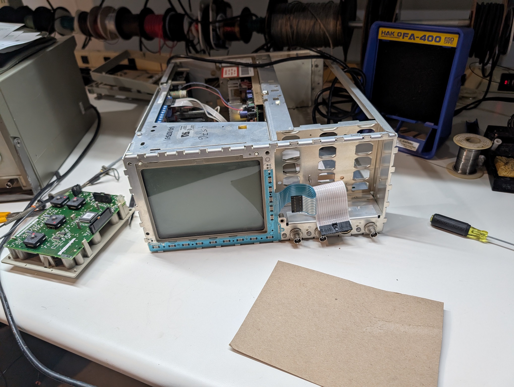


Overall, I am not impressed with the PCB routing by Tektronix, or whoever did it for them. Even if this is not the problem.
I guess, if these capacitors leaked, it is not their fault. But what I do not know, how those vias got oxidized. Vapors from leaking caps?

Worst case, I will buy a new board, but only if the price makes sense.

People who do not drink, do not smoke, do not eat red meat will one day feel really stupid lying there and dying from nothing.
#2

So, today I had to go to get the Real ID drivers license, and as this is close to my work, I used the opportunity to pop up at my workplace, say some hi's, immediately being asked to help here and there, and then I had time to use solder tweezers to remove the aluminum electrolytics that leaked.
I measured them with my Fluke, and it refused to tell me the value. It was kinda infinite. Despite them not being shorted.
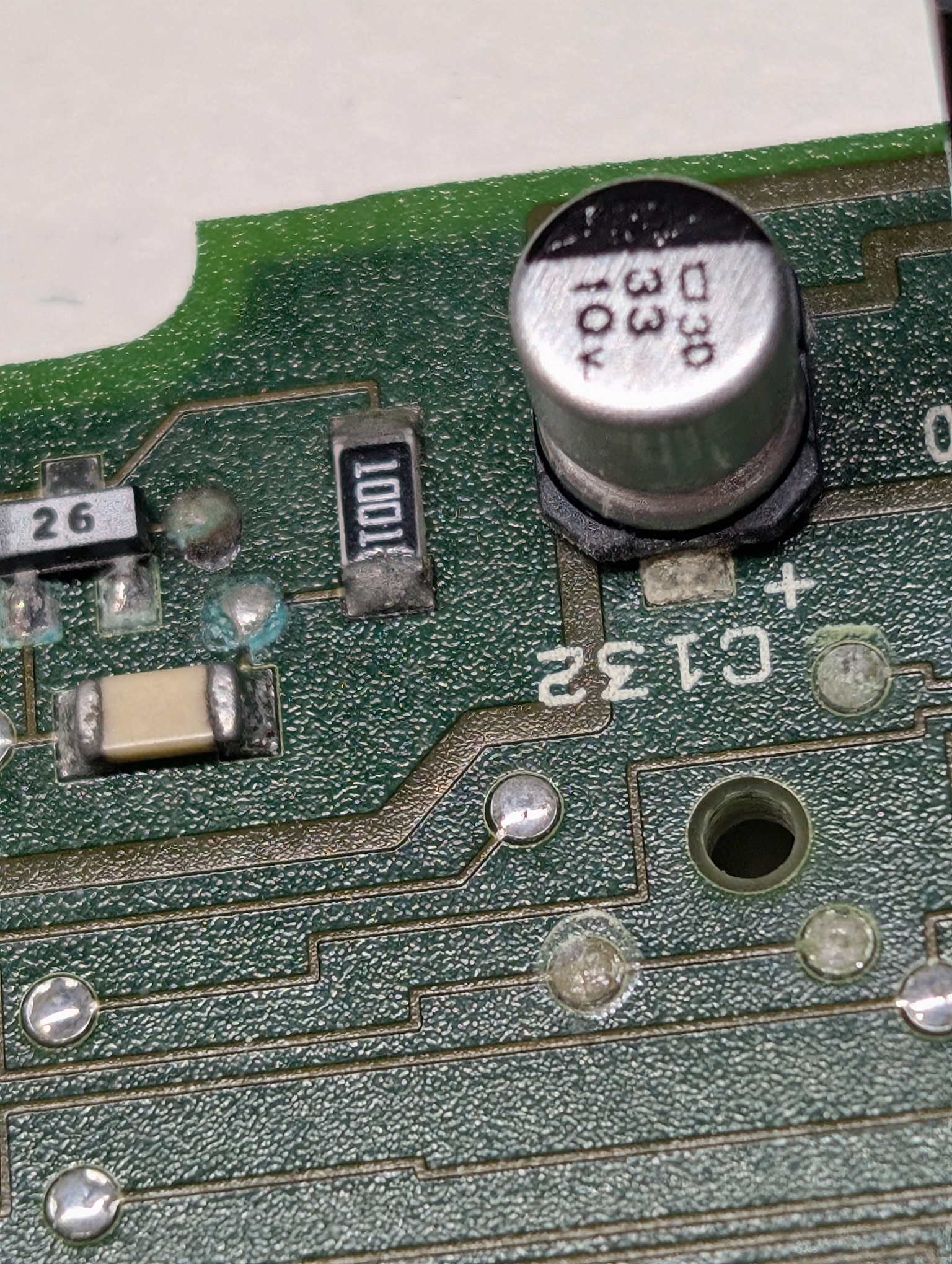
So, I cleaned the board again, touched up some vias, put a bandage on the trace that got etched right by the via (invisible but the continuity was not there), though the trace is from the encoder and would not result in the issue I was seeing; then I replaced the electrolytics (33uF 10V) with X5R 22uF 25V caps: the value is sufficient and the size allowed me to solder them to the footprint.
C131 and C132.
The bandage is seen at the right upper corner of the CPU.


So, full of hope, I installed the board and...same issue. Wakes up in indeterminate mode.

The problem is, there is no schematic for the Front panel board. I found the sch for a similar scope, but it is not exactly the same. But the interface is the same, and so I decided to look at the last signal I never looked at, and which I should've done, considering the CPU wakes up in different modes: the RESET.
Which I did.
It was floating close to the Low level. And...it did not connect to any of the the connector's pins, especially to the pin 9, which is the RESET.
I traced the trace.  I could not see under the connector, and it was mu guess that the pin 9 should connect to the processor's pin 18 (RESET), which has RC to GND on it.

So, this is the via, after which I could see the beginning of the stup, that supposedly went to pin 9, and which was the last point that would show connection to that RESET pin of the CPU. The via is pointed to by the red arrow. And the Pin 9 of the connector (RESET) is pointed to by another arrow.


So I put a short between them on the bottom side.


I installed the board, and it immediately worked!

So I decided to stop for today and wait 'till tomorrow, as when the board is cold, the symptom appears at the very first try. I think it is going to work.

People who do not drink, do not smoke, do not eat red meat will one day feel really stupid lying there and dying from nothing.
#3

Nice work, Mike. GL


Users browsing this thread: 1 Guest(s)
[-]
Recent Posts
Philco 42-345 Restoration/Repair
Yes, 57 is an electrolytic cap that should be 12 mfd 400 volts according to the parts list from the Phorum library schem...RodB — 06:01 PM
Philco 42-345 Restoration/Repair
Looks like if I am reading it correctly it looks like the silver capacitor#57 that appears to be a replacement is of a l...osanders0311 — 05:09 PM
Philco model 38 code 121 not receiving signal.
Thanks Arran. Yeah this plastic is pretty thin. It's a little thinner than the original stuff. It kinda reminds me of p...Stormlord5500 — 04:37 PM
Testing a speaker and output transformer Trutone A2-G
The equivalent of one short turn is basically the same as that of a shorted load. If it is the primary's turn, then the ...morzh — 03:53 PM
Testing a speaker and output transformer Trutone A2-G
I've never had an output transformer become shorted, the failure mode is usually an open primary, or in a center tapped ...Arran — 03:52 PM
Philco model 38 code 121 not receiving signal.
As long as the plastic sheeting isn't too thick, I think that the thickness of photographic film would be just about rig...Arran — 03:19 PM
Philco model 38 code 121 not receiving signal.
Well why not! :lol:Stormlord5500 — 03:14 PM
Philco model 38 code 121 not receiving signal.
Good luck next thing you know you will be winding coils just for the fun of it. DavidDavid — 11:29 AM
Testing a speaker and output transformer Trutone A2-G
morzh Short-circuited turns can be considered as a half-dead transformer. But on this case transformer will hot and s...Vlad95 — 11:01 AM
Testing a speaker and output transformer Trutone A2-G
I am not sure how a transformer could be weak. It could be inadequate, but only when you replace the original with somet...morzh — 09:56 AM

[-]
Who's Online
There are currently 2187 online users. [Complete List]
» 1 Member(s) | 2186 Guest(s)
Avatar

>