Posts: 18,427
Threads: 622
Joined: Oct 2011
City: Jackson
State, Province, Country: NJ
So, put the cap in, restored the wiring.
Powered on.
Strong hum on both bands.
At one spot on the dial there was a very faint reception.
Well, can't get lucky all the time.
Plus it was Christmas, so the set might've felt as resting and not working.
People who do not drink, do not smoke, do not eat red meat will one day feel really stupid lying there and dying from nothing.
Posts: 18,427
Threads: 622
Joined: Oct 2011
City: Jackson
State, Province, Country: NJ
So, after quite a bit of troubleshooting and attempted IF signal through, which came weak and with lots of hum, I eventually decided to re-take voltages and realized the 2nd IF Cathode is high, 38V.
So, what happened was, during the recap I severed 100 Ohm Cathode feedback resistor, leaving just the cap.
I re-instated the resistor, and the radio immediately started playing, and it does play great on both AM and FM. Big booming sound with the chassis outside the cabinet (I doubt the backelute cabinet will add much).
I will still go through the IF and the bands alignment, as I disturbed the IF trying to peak.
I will shoot a little video later and place it with my Youtube channel.
Also, I realized that the Selenium Rectifier was giving me lower than required voltage: Where I needed 130V on the first rectifier cap, I was getting below 100V, if not below 90V.
I put a 1N4007 diode and added an 82 Ohm resistor.
From the measurements the resistor drops 6V, and so the dissipatrion is 0.45W or so, but the reesistor (a ceramic 5W) gets uncomfortably hot, can't be touched, so I am not sure what to do: the voltage is a bit higher than needed at 117VAC (and it is 127VAC at my place) but the larger the resistor the hotter it will get.
I could reinstate the SR and the 22 Ohm resistor that was there, I am sure it will work, but then the voltage will be too low.
People who do not drink, do not smoke, do not eat red meat will one day feel really stupid lying there and dying from nothing.
Posts: 5,654
Threads: 56
Joined: Sep 2008
City: Sandwick, BC, CA
Mike,
The selenium rectifier is tired in your set, and will only get worse. I have an RCA three way portable that was working fine for years, and now it will only play with the line voltage cranked up to 125 volts, the B+ coming off of the selenium is maybe 90 volts with a load on it. This is a model with a tuned RF amplifier stage too, so the poor performance was noticeable. I'm not sure what to suggest to reduce the input voltage, maybe a bucking transformer, finding a large value cap that is compact enough to only drop 10 volts would be a problem.
Regards
Arran
(This post was last modified: 12-30-2025, 07:32 PM by Arran.)
Posts: 18,427
Threads: 622
Joined: Oct 2011
City: Jackson
State, Province, Country: NJ
I wonder if I should use the hole for the SR as a holder for a solder post and assemble the resistor outside. Or even use the SR itself, one point.
People who do not drink, do not smoke, do not eat red meat will one day feel really stupid lying there and dying from nothing.
Posts: 5,654
Threads: 56
Joined: Sep 2008
City: Sandwick, BC, CA
Mike;
I think I used one of the legs on a S.R to mount a silicon diode, and left the other leg open, as long as one end is not connected to chassis it will work this way. One of those chassis mount "Arcol" type resistors would work for the dropper, though a 20 watt wire would would also work if it's well ventilated. Come to think of it a lot of radios with a S.R had vent holes punched through the chassis, and bottom cover, at least that RCA portable did, it used a candohm to drop the B+ for the tube filaments.
Regards
Arran
Posts: 1,797
Threads: 55
Joined: Feb 2015
City: Roseville, MN
Mike, I think the bucking transformer is the answer. If there's not enough room for it then there's a device you are probably aware of but I can't remember the name, something like NIP or NPR, it goes in series with the transformer primary. They get warm but not too hot to touch. Looks like you need to drop 10 volts so you would use two in series. They look like oversized ceramic caps.
Just checked Mouser and found NTC Thermistor. Maybe that's the one.
Posts: 181
Threads: 7
Joined: Apr 2025
City: SPRUCE GROVE
State, Province, Country: Alberta
Guys, don't break your brains about 10v. +/- 20% is a normal parameter spread by any standard. Don't push perfection to the point of insanity.
If you want to work, lie down and sleep, and everything will pass.
Posts: 1,797
Threads: 55
Joined: Feb 2015
City: Roseville, MN
Vlad, I think Mike is being cautious because the mains line is 127 and that results in a substantial increase to filament voltage, probably over 7 volts. Those power plants in NJ get real excited.
Posts: 1,420
Threads: 41
Joined: Jan 2014
City: Wellborn Florida
OK call me crazy but I tried this just to see if it would work. String series of 10 1N4007 would drop voltage app 7 volts plus a 50 ohm resistor gets the voltage down were it would have been in 1955. Fits right were the old SD was located. Like I said crazy but works. David
Posts: 18,427
Threads: 622
Joined: Oct 2011
City: Jackson
State, Province, Country: NJ
A few uF cap will drop as much AC without dissipating. I just need to calculate 10V drop. This is if I only want to keep the filaments happy. Which is fine, the tubes themselves are 250V types.
Let's see.
I need to drop 10V at 150mA.
The current active impedance of filaments is 760 Ohms at 114V.
I need 847 Ohms to keep 150mA at 127V.
I need 374 Ohm of capacitive impedance.
So I need 7.1 uF cap (have Solen 6.8uF).
And the filaments are important as extra 10V makes it app. 1.4V extra per tube, and while for 19 and 35V ones it is small, for 12V tubes this is more than 11.5% rise or 25% rise in power dissipation. Nothing to sneeze at.
But.
Thing is, if I decided to get rid of the resistor after the diode (it does not affect the filaments, but does affect the tubes voltages, which would be OK), my voltage on the primary cap would be in excess of the 150V of the cap's rating. I don't want that.
People who do not drink, do not smoke, do not eat red meat will one day feel really stupid lying there and dying from nothing.
Posts: 18,427
Threads: 622
Joined: Oct 2011
City: Jackson
State, Province, Country: NJ
So here's the real problem.
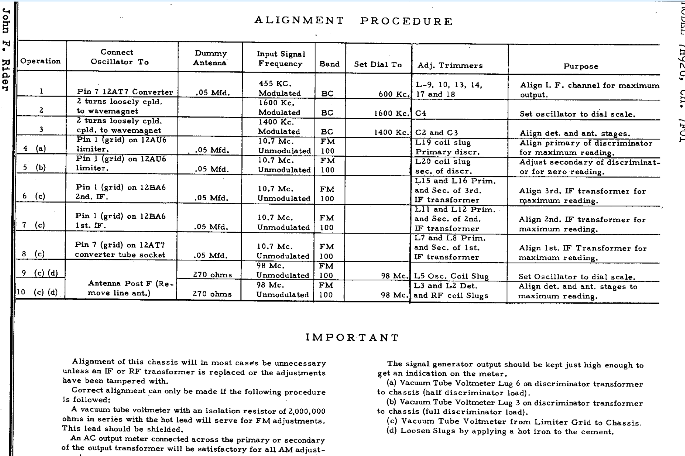
I attempted alignment of the FM.
The procedure asks to put an unmodulated FM 10.7 MHz signal (which is just the sinewave, no FM) to the grid of the Limiter (12AU6).
Then it asks to put the meter (I use a DMM) between the pin 6 of the discrimination xfmr and the GND and max it out.
This is not really maxing out.
Then move the DMM probe to the pin 3 of the xfmr and trim it down to Zero. Or so I understood. Not happening either.
Does anyone have experience with this or similar radio FM alignment?
This is the procedure.
This is the sch.
People who do not drink, do not smoke, do not eat red meat will one day feel really stupid lying there and dying from nothing.
Posts: 181
Threads: 7
Joined: Apr 2025
City: SPRUCE GROVE
State, Province, Country: Alberta
Let's see.
I need to drop 10V at 150mA.
The current active impedance of filaments is 760 Ohms at 114V.
I need 847 Ohms to keep 150mA at 127V.
I need 374 Ohm of capacitive impedance.
So I need 7.1 uF cap (have Solen 6.8uF).
And the filaments are important as extra 10V makes it app. 1.4V extra per tube, and while for 19 and 35V ones it is small, for 12V tubes this is more than 11.5% rise or 25% rise in power dissipation. Nothing to sneeze at.
Uh, the calculations are a bit long.
If we limit ourselves to Ohm's law, then to damp 10 V at 150 mA, we need add resistance of 66 ohms and a power of 1.5 watts.
If you want to work, lie down and sleep, and everything will pass.
(This post was last modified: 12-31-2025, 09:45 PM by Vlad95.)
Posts: 18,427
Threads: 622
Joined: Oct 2011
City: Jackson
State, Province, Country: NJ
Vlad,
I was calculating a capacitor, not a resistor, in order to drop 10V at 150mA and not dissipate any unnecessary power.
Also. You of all people should now that dissipating 1.5W is nothing to sneeze at: a 5W resistor dissipating 1.5W will get really hot. And it takes space as well.
I am dissipating at this point 0.5W om an 82 Ohm / 5W resistor, and the temperatire I measured yesterday (my finger could not accurately assess it because it got a little burnt) with a thermocuple was in excess of 150F. Again, at mere 0.5W. With a decent size porcellain 5W resistor.
So, the calculations are necessary to accurately get the capacitive value as the resistor, while can be used, is less convenient and I do not want it.
People who do not drink, do not smoke, do not eat red meat will one day feel really stupid lying there and dying from nothing.
Posts: 181
Threads: 7
Joined: Apr 2025
City: SPRUCE GROVE
State, Province, Country: Alberta
Using a capacitor as a ballast isn't a very good option, especially for filaments. The downside is a very high charging current surge during startup. I had a sad experience in the distant past when I tried to get by without the scarce fluorescent lamp ballasts by using capacitors. As a result, the filaments of the even more scarce lamps burned out. And that was over half a quarter of a century ago.
If you want to work, lie down and sleep, and everything will pass.
Posts: 18,427
Threads: 622
Joined: Oct 2011
City: Jackson
State, Province, Country: NJ
This does not apply here. I've done this many a time.
There is no large charging current as the cap's impedance
A very small part of the overall impedance. And so even if removed (which would emulate the inrush - inrush is a short, same as a removed cap) it will increase the current no more than back to its original 166mA instead of 150mA.
That is, your "inrush" is limited by the resistance of the filament string.
Not the end of the world by any stretch.
The fluorescent lamps is a very differently behaving situation. That, entirely different.
People who do not drink, do not smoke, do not eat red meat will one day feel really stupid lying there and dying from nothing.
Users browsing this thread: 4 Guest(s)
|
|
Recent Posts
|
|
Stromberg Carlson 1500 Squeal
|
| And life just keeps getting more complicated. By dconant.
Dittos'Jimradio — 08:01 AM |
|
Plug Voltages Needed For A 1943 CRV-20130 Power Supply
|
| That looks a lot like an aircraft connector of some kind, even if it's a U.S.N power supply. I have a book somewhere abo...Arran — 02:56 AM |
|
Plug Voltages Needed For A 1943 CRV-20130 Power Supply
|
| hello david,
I have a similar generator in my collection that features a cast iron, single-cylinder Briggs & Stratt...radiorich — 01:00 AM |
|
under chassis parts locator diagram for 1938 Zenith 9s262
|
| Has anyone gone to the trouble of creating an under chassis parts locator image? Yes, I can identify components by foll...bobloney — 08:57 PM |
|
Plug Voltages Needed For A 1943 CRV-20130 Power Supply
|
| Try looking at this site the book mark is for a old generator that I was given. David https://radionerds.com/index.ph...David — 08:36 PM |
|
Plug Voltages Needed For A 1943 CRV-20130 Power Supply
|
| Hello Everyone,
I am looking for voltage identification for all the pin positions on the socket of a CRV-20130 power su...Tonym4704 — 08:16 PM |
|
Philco P45-6365 Universal Transformer Instruction Manual
|
| Can anyone guide me to where this may be found?GRG — 03:00 PM |
|
54C Complete Teardown/Rebuild
|
| I don't think that I have encountered a 12Z3 before, curious how it uses one of those but includes a #43, which is a 25 ...Arran — 02:17 PM |
|
HiFi (Chifi) tube amp build - but my own design.
|
| It's the other forum. I'm also in DIY, but mostly read there. Honestly, I kinda jumped into this without much thought to...TV MAN — 10:43 AM |
|
Philco 71 Code 125
|
| Hello,
I am in need of a schematic for this radio. Mine has the three separate circular tube shields and a shadow me...dconant — 08:06 AM |
|
Who's Online
|
There are currently 2270 online users. [Complete List]
» 1 Member(s) | 2269 Guest(s)
|
|
|

|
 
|







