Zenith 6S254 Intermitten Reception
Posts: 348
Threads: 20
Joined: Nov 2016
City: Cromwell
State, Province, Country: CT
If you feel this is an oscillator issue, check C7 the 0.002 capacitor in the OSC section. The list doesn’t say so, but these are usually mica caps, even though the value typically seems it should be paper. They have B+ on them and are suspect for leakage.
I replaced one in a set I had with a film cap, while it worked, the osc drifted. You can use a film cap as a temp test, just don’t damage the old one if it turns out to not be the problem. A 1or2% mica is a suitable replacement that worked for me.
Tony
“People may not remember how fast you did a job, but they will remember how well you did it”
Posts: 18,427
Threads: 622
Joined: Oct 2011
City: Jackson
State, Province, Country: NJ
About C7:
All non-micas should've been changed by now.
In the #137 post it was asked "3. The oscillator's (the right side) of the band switch."
That is all the osc circuitry that is right of that Switch #6. Which has C7 in it.
If it is a mica cap, it probably is OK. If it is paper, it should be replaced.
But. In the Post #1 it states: "What I have done to this radio is replaced all caps, ecaps, micas and resistors. "
Unless that one is inside the coil and was not touched.
People who do not drink, do not smoke, do not eat red meat will one day feel really stupid lying there and dying from nothing.
Posts: 18,427
Threads: 622
Joined: Oct 2011
City: Jackson
State, Province, Country: NJ
https://www.nostalgiaair.org/pdfs/Zenith...-254AT.pdf
An interesting mod was done in the AT (export) version. The sole change was, the B+ was brought to the oscillator through an additional 12K/4uF (R12/C21) filter, taken before the Feld coil, not after.
Supposedly they improved the stability this way, plus protected it from power fluctuation in foreign countires' grids.
People who do not drink, do not smoke, do not eat red meat will one day feel really stupid lying there and dying from nothing.
Posts: 555
Threads: 89
Joined: Jun 2022
City: Marion
State, Province, Country: NY
Yes R3. The wire I pulled was one side of the resistor. So the 7.5K resistor is in there now with one side of the 10K still connected. I wanted to verify the 10K was reading 10K. It was real close. Yes all caps have been changed including micas (domino style including C7). If there is a cap in the osc can I did not do that. I used 5% silver micas. The problem was happening prior to changing the micas. The parts list shows two .002 caps. I saved the old parts, one is a mica and the other is paper so I'd say C7 is not in the can also I can see it in the radio where it is in the schematic.
It is confirmed the radio craps out on SW too.
Posts: 18,427
Threads: 622
Joined: Oct 2011
City: Jackson
State, Province, Country: NJ
(sigh)
You don't have a scope, do you...
People who do not drink, do not smoke, do not eat red meat will one day feel really stupid lying there and dying from nothing.
Posts: 555
Threads: 89
Joined: Jun 2022
City: Marion
State, Province, Country: NY
I do but it is not very good. Shall I try that mod you spoke of?
Posts: 1,799
Threads: 55
Joined: Feb 2015
City: Roseville, MN
Tony,
Dan replaced all tubes, caps and resistors days ago. He and Mike are well outside the box now.
Posts: 18,427
Threads: 622
Joined: Oct 2011
City: Jackson
State, Province, Country: NJ
Which mod are we talking about? Oh, the extra RC filter before the R3?
We could, but before we start modding things...
1. We do know that the radio probably did not leave the factory with this problem. So introducing the mods before understanding the reason behind the problem has less chances of working, and even if it does, we are masking the problem, by fixing what we still have not understood.
2. I would suggest this. Put a scope to the R2 (the one across the coil), to the pin that is the opposite to the one that connects to the R3.
Tune into the station.
Then connect the scope. Make sure it does not ruin the reception. It should be your "good behavior" reception.
Make sure you could see the oscillation well, sync the scope on it to make it stable. Note (write down/photograph) the frequency, amplitude, jitter (if possible, otherwise just the stability of it).
Then wait 'till the crap-out.
Note, again, the signal's parameters: the amplitude, frequency, jitter.
If the scope is digital, it is easy; else you will have to calc it yourself.
3. If no crap-out happens, it could be possible your scope GND is doing it. Then connect the scope through an isolation xfmr.
Then we will proceed, depending on the results.
People who do not drink, do not smoke, do not eat red meat will one day feel really stupid lying there and dying from nothing.
Posts: 555
Threads: 89
Joined: Jun 2022
City: Marion
State, Province, Country: NY
I will hold on the mod. Hopefully my scope can read that. I'll try tomorrow. Scope is a Conar model 251 one that I built as a kit long time ago when I took a home study course from National Radio Institute back in the 80s. It was all done through snail mail. Did solid state training.
Radio is connected to an iso now would I connect both to iso if no crap out? Scope does not have an AC ground prong.
Posts: 18,427
Threads: 622
Joined: Oct 2011
City: Jackson
State, Province, Country: NJ
So...when you said you touched the GND to the radio, it was actually working via isolation transformer?
And the problems only occur while working through it? Have you tried to work directly from Mains?
No, only connect one device to ISO xfmr at a time.
At some point we might try both connected to it, but only if your xfmr has enough oomph.
People who do not drink, do not smoke, do not eat red meat will one day feel really stupid lying there and dying from nothing.
Posts: 555
Threads: 89
Joined: Jun 2022
City: Marion
State, Province, Country: NY
Yes I have done direct to mains. The ground I speak of is antenna ground via a pipe in the ground outside the house.
Posts: 18,427
Threads: 622
Joined: Oct 2011
City: Jackson
State, Province, Country: NJ
The pipe outside of the house is still connected to your house ground. This is why it is the GND.
People who do not drink, do not smoke, do not eat red meat will one day feel really stupid lying there and dying from nothing.
Posts: 1,799
Threads: 55
Joined: Feb 2015
City: Roseville, MN
Hi Dan, Mike,
Could this possibly be a ground loop problem? I don't remember if Dan mentioned that the chassis is tied to the power ground. If the earth ground and chassis ground are involved in a loop would that interfere with the oscillator?
Just kicking the "ground" for ideas.
Posts: 555
Threads: 89
Joined: Jun 2022
City: Marion
State, Province, Country: NY
There is no chassis ground to mains (two wire plug).
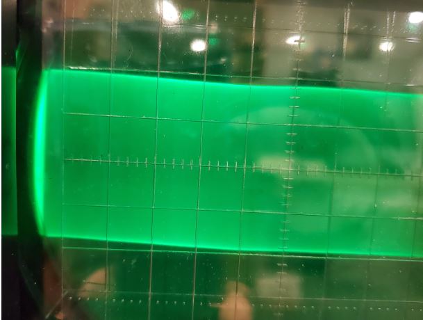
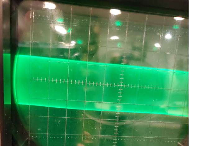
Turned on radio and it was poor reception. Connected scope and got a little over one and a half. Forgot to take picture. Did the disconnect antenna ground and reconnect now good reception. Scope shows almost two. Not sure what you call them. Picture show in good reception with almost two. Notice I could not not get individual pulses at any time. So does this say oscillator is weakening?
Posts: 555
Threads: 89
Joined: Jun 2022
City: Marion
State, Province, Country: NY
Here is the picture for poor reception.
Users browsing this thread: 5 Guest(s)
|
|
Recent Posts
|
|
54C Cabinet Refinish
|
| hello Roy,
I’d follow Arran’s suggestion and use automotive gasket material, which I keep around for situations like th...radiorich — 10:22 PM |
|
Philco 71 Code 125
|
| This might be one of those cases where it's a ground to an AC voltage and B- to DC.RodB — 08:22 PM |
|
Philco 71 Code 125
|
| Really Rod? I know you would not steer me wrong but AI say this is a short circuit? What if I moved the 6 volt center ta...dconant — 06:40 PM |
|
54C Cabinet Refinish
|
| Roy;
Personally I would have left the asbestos alone if it were my set, but you can find a modern substitute that som...Arran — 04:51 PM |
|
Philco 71 Code 125
|
| Looks like that might be the B- buss, so that would be correct.RodB — 01:32 PM |
|
Philco 71 Code 125
|
| I noticed on the code 121 schematic the center tap for the 6 volt winding and hv winding are tied together. Is this corr...dconant — 12:16 PM |
|
Philco 45-6365 Universal IFT Instruction Manual
|
| The Philco Parts Catalog for 1942 shows it as usable for 175 kHz, 260 kHz, and 465 kHz. The instructions will show how t...DaleHCook — 11:19 AM |
|
Stromberg Carlson 1500 Squeal
|
| Hello Rob,
I agree with you—I have one here at my house that I need to check out. It’s way over-engineered just to make...radiorich — 11:05 AM |
|
My Atwater Kent 84
|
| Well getting around to restoring my AK84. Mike was a big part in me being able to snatch this one a few years ago. I won...462ron — 10:57 AM |
|
Plug Voltages Needed For A 1943 CRV-20130 Power Supply
|
| The engine is a B&S 23 inch cast Iron holds 2 quarts of oil. The Generator is a 4 pole 1800 rpm mine was made in 195...David — 10:51 AM |
|
Who's Online
|
There are currently 2639 online users. [Complete List]
» 1 Member(s) | 2638 Guest(s)
|
|
|

|
 
|








