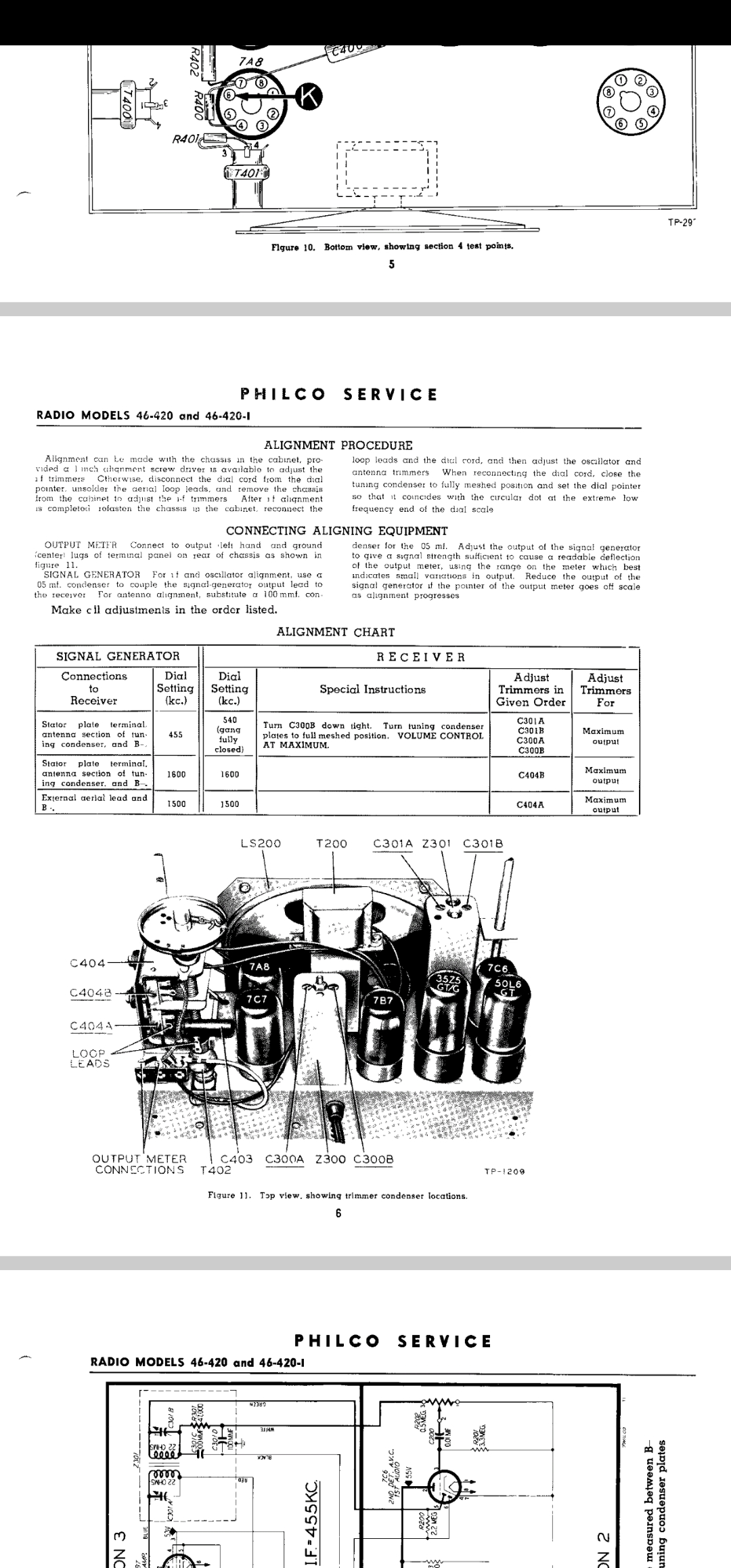
I just got done recapping a philco 46-420. It works ok however the internal antenna is missing. I could see where it was once glued to the case. Right now I'm using a clip lead attached to the lug on the tuner the antenna was connected to, the audio is noisy but it pulls in strong stations anything slightly weak is just noise. As an experiment I tried to use a am loop antenna from like a early 2000 stereo attached between the tuner and ground, this cleaned up the sound but the radio seemed like it wasn't as hot, then I tried to align it and I wasn't able to get a good Peak on c404A. In the attached alignment picture you'll see where it says Loop leads, the radio will sort of work with a clip lead or one leg of the loop antenna attached to that position on tuner, if I attach the other leg if the loop antenna to the spot marked loop leads on t204 the radio gets nearly silent and I can't get Peak audio out of c404a it's always very weak. What can I do for an antenna? The only station that plays music is am 1250, and it's a fairly weak station so I'd really like to try to get everything I can out of this radio so I'm more likely to use it.
Hello apERNA1985,
The problem is that the antenna is part of the front end of the tuning circuit in this radio. I have a GE model J-64 that’s also missing its antenna. The set requires the correct impedance and resistance for the antenna to be properly connected in the circuit. It’s like a string of small, multi-colored incandescent Christmas lights—if one is missing, the circuit won’t work. And if you just bridge the two connections with plain wire or the wrong bulb, the rest of the bulbs will burn out.
Hello apERNA1985,
Sure, but they’re not using a ferrite rod—just loops of wire. Here’s a screenshot from Ken’s radio video showing what the antenna looks like, and the schematic also indicates its ohms value.
Sincerely Richard
I’d make a cardboard box or wooden form sized to fit the inside of the antenna, wind the wire around it to replicate the original, and then glue it to the inside of the cabinet.
Hi apERNA, I have the same radio. From what my eyes can determine, it looks like there are 18 loops of wire in that antenna glued all around the inside perimeter of the cabinet. I measure 3 ohms and .022” diameter of wire, 24 guage. Hope this helps!
Quote:Hi apERNA, I have the same radio. From what my eyes can determine, it looks like there are 18 loops of wire in that antenna glued all around the inside perimeter of the cabinet. I measure 3 ohms and .022” diameter of wire, 24 guage.
apERNA,
This a start and good data. If 462roncan provide additional data:
The circumference of the loop in inches?
The turns direction when facing the rear of the radio, CW or CCW?
At the start of the winding at the very rear of the radio, the number of turns to a tap or the turns as a coil?
The next winding or tap, the number of turns?
Which connection to the frame of the variable condenser and which tap/connection connects to the stator of the tuning condenser? This the most important winding, turns are critical if the inductance is to match the broadcast band.
I do not have the circuit handy but, any auxiliary winding may be for the use of an external antenna and ground.
Knowing the circumference, fabricate a circular form of that circumference that can support the full width of the winding with some additional with for fabrication of the winding. Seal the form if required, place spots of double sided tap in at least eight locations uniformly place around the perimeter of the form, allow some hangover so the tap can be grabbed and pulled out. Use nylon reinforced packing tape of the full width or greater sticky side up allowing the double sided tape to grab the non-sticky side. One layer of the reinforced tape should work but additional if the tape is not wide enough.
The sticky surface can now accept the enameled wire, wind with some tension and no spacing all of the turns leave ample ends for connections. and taps. cover the winding with more reinforced tap one or two layers.
Pull out the double sided tape, the coil can now be worked off the form and fitted into the cabinet its O.K. if its a bit large or small, leave a hump or jump a corner.
Final resonance adjustment is done at 600khz by adding or removing partial turn of the antenna winding, NOT the A/G winding (smaller of the two). A slight fold back of the entire coil can also reduce the inductance. If it needs inductance add to the turns of the larger winding across the tuning condenser.
This inductance is a "rocking" adjustment, meaning there is a set/reset of dial position until resonance is achieved at 600khz.
Be sure dial cursor is correctly located before alignment.
Good Luck!
Chas
Pliny the younger
“nihil novum nihil varium nihil quod non semel spectasse sufficiat”
Hi Chas, as for circumference, apERNA can try and measure the inside of the cabinet with all its nuances to get a number. It will be tedious for sure to do this. I would suggest maybe making it with a few extra turns and then see how it resonates, possibly removing some loops. The antenna has no taps, just one big coil with 2 ends.
The antenna likely needs to be one that was used with a 10-365 pF (mmf) cap for the broadcast band. The vast majority of "AA5" Radios used this capacitor value for the convertor. Your set is the 6 tube variant with a tuned RF stage. This stage also used a 10-365 uF section of a 2 gang tuning capacitor. The convertor stage is not tuned by this capacitor. ("AA5" is what collectors call the "All American 5 Tube" radio as the vast majority of radios designed between about 1940 to the end of tube table radios used this circuit). If you can find a loopstick that was used on an old 5 tube or 6 tube set, this should work.
Remember that any loop antenna, (actually any antenna except a vertical one) and especially a loopstick antenna are extremely directional. When using, turn the loopstick (or the entire radio) till the signal is strongest and the noise is weakest. Some radios and many of the 1970s era stereo receivers had the loopstick mounted so it could be rotated without rotating the radio. Your set was designed for a loop antenna which was fixed into the cabinet, and you had to rotate the radio for best reception.
This radio has an antenna transformer in series with the loop antenna. This transformer allows for the use of an external antenna. If you are substituting a loop or loopstick from another set, you may have to remove this from the circuit.
Radios were sold based on location of use. In cities, the 5 tube version or even a 4 tube superhet (Convertor and tuned IF transformer bit no IF tube), Detector / AF, Output and Rectifier. were sold. In fronge areas, the 6 tube version (RF Amp, Convertor, IF, Detector / AF, Output, Rectifier) are sold. Your set should be more sensitive than the standard AA5 such as a 42-PT94
One advantage of a loopstick over the regular loop antenna is that it may be less susceptible to some of the more recent radiated noise from all the electronic pollution that exists from switching power supplies, CFLs, LEDs, the Internet of Things (IoT), etc.
"Do Justly, love Mercy and walk humbly with your God"- Micah 6:8
"Let us begin to do good"- St. Francis
Mrfixr55, I forgot that the radio is capable of using an external antenna. Am I putting myself through a wild goose chase for no reason. Could I just hook up to the external antenna Terminals and forget all about the missing internal antenna? Or are they intended to work together?
The issue is that the inductance of that coil is only part of the inductance of the total antenna that the radio was designed for.
In older radios that required an outdoor antenna, the inductance of the secondary of the antenna transformer matched the tuning capacitor to receive the desired range. In your set, the secondary of the antenna transformer and the loop, in series provide the specific coil inductance to receive the broadcast band with strength.
Your profile says that you live in Paramus, NJ, so you should be getting blasted by several NY Metro stations. I think that WABC's antennas are in the Meadowlands. You should receive strong signals from WFAN (660), WOR (710), WABC (770), WCBS (or whatever they call themselves now at 880), and WINS (1010).
If you want to try an outdoor antenna, leave the one that you are using, in series with the antenna coil
The tuning condenser in your set is a 2 gang condenser. The Oscillator section is at the top; the RF section is at the bottom. The loop should be connected between the stator tab at the bottom level of the tuning cap and Terminal 3 of the antenna coil. Terminal 4 should go to the AVC Line.
The link below takes you to the official Philco service document for this set. The terminals for the antenna are marked on pgs 62 and 63 0nthis document..
Remember if the loop or loopstick that you are using is not providing a strong signal, reverse the connections. It may be out of phase with the antenna coil in series with it. When you get the connections that give you the strongest signal, you should be pulling the stations listed with absolutely no problem other than local interference.
Remember that loop and loopstick antennas are directional so rotate the loop, loopstick or radio for best signal with least interference.
Ther are "trimmer" condensers on the side of the tuning condenser (condenser and capacitor or "cap" are interchangeable). Adjust by peaking the one on the oscillator to ensure that the frequency received matches the frequency on the dial. Peak the lower trimmer (the RF trimmer) for strongest signal. The IF transformers can be peaked in the same manner. Mark the current position and don't turn excessively in either direction. A peak should be found for each adjustment. If you can't make a difference, return to marked position.
Once you are satisfied that you can receive the listed stations, try the weak station that you are trying to receive. Try an external antenna at this point.
What are the station call letters, frequency and location?
Keep us posted. This radio is the iconic "Hippo" style and should be very good at receiving signals. I wouldn't call it "HiFi", but the 6X4 speaker provides better performance than the standard 4" speaker.
"Do Justly, love Mercy and walk humbly with your God"- Micah 6:8
"Let us begin to do good"- St. Francis