GE Model 210 AM Sensitivity
Posts: 711
Threads: 46
Joined: Sep 2009
City: Lapeer, MI
State, Province, Country: USA
I'm continuiong the discussion on the GE 210 from the "August Finds and Losses" to here where it is probably more appropriate. Mr. Fixr, I have done the resistance measurements for the first and second AM IF transformers. They conform to the given values of 15 ohms on both the primaries and secondaries. I recleaned the band switch and measured the continuity thereof and contact is securely made, both AM and FM. I found a connection from the Variable cap to the antenna that was loose and I re-soldered. Very little change in sensitivity. I will probably look at performing an alignment tomorrow. I rarely align a radio if the tracking is only off a little, but that seems to be the next step. Thanks to all who have contributed to finding an answer to this problem. Joe
Courage will follow when Faith takes the lead.
(This post was last modified: 08-10-2026, 01:51 PM by Joe Rossi.)
Posts: 711
Threads: 46
Joined: Sep 2009
City: Lapeer, MI
State, Province, Country: USA
I aligned the radio after church this afternoon. I was hoping that someone had taken a screwdriver and 'adjusted' all the twisty things. No change to sensitivity. The radio will now join my others on display. It's still a handsome radio. Thanks to everyone who showed encouragement. Joe
Courage will follow when Faith takes the lead.
Posts: 5,656
Threads: 56
Joined: Sep 2008
City: Sandwick, BC, CA
Are you sure you are not citing the wrong model number, the G.E 201 seems to be a single band AM only radio with trimmer tuned IF cans, not slug tuned? This is the one that comes up as a model 201 https://www.radiomuseum.org/r/general_el_201.html https://www.tuberadioland.com/ge200_and_201_main.html
Regards
Arran
Posts: 348
Threads: 20
Joined: Nov 2016
City: Cromwell
State, Province, Country: CT
I’m guessing this is the schematic for your radio, a model 210.
GE 210
Looks like a slug tuned IF set.
Tony
“People may not remember how fast you did a job, but they will remember how well you did it”
Posts: 711
Threads: 46
Joined: Sep 2009
City: Lapeer, MI
State, Province, Country: USA
Tony, Yes, that's the one. As I mentioned previously, and per recommendations, I've measured the resistance of the primary and secondary of both AM IF's and they are supposed to be 15 ohms, and they measured between 15 and 16 ohms. I've tapped the cans to see if there is anything to cause noise, I've seen no electrical arcing, and I've aligned the stinker. I've checked each connection for cold/loose solder joints. No joy. Do you have any ideas? Thanks, Joe
PS: I haven't checked the Mica caps; I will do that now.
Courage will follow when Faith takes the lead.
Posts: 711
Threads: 46
Joined: Sep 2009
City: Lapeer, MI
State, Province, Country: USA
There are seven 47mmf (.047nf) Mica's in the circuit. My LC1020E LCR meter measures them as follows: 5.4nf, 1.03nf, 1.33nf, 2.57nf, 3.4nf, 4.7nf, and .059nf. That last one is the only one within tolerance. I bought six when I purchased the tubes from Jim Cross at VTI. I am going to now replace them one-by-one beginning with the most ouit of spec on down and see what, if any, difference that makes. Stay tuned.  Joe
Courage will follow when Faith takes the lead.
Posts: 1,799
Threads: 55
Joined: Feb 2015
City: Roseville, MN
That should be interesting. It's not common to see mica caps increase in value. Could be a bad lot. I wonder if they may have contamination of some kind.
Posts: 711
Threads: 46
Joined: Sep 2009
City: Lapeer, MI
State, Province, Country: USA
Rod, The problem is UE, User Error! I tested the caps in-circuit. Out of circuit they are within tolerance. So back they went. My last straw is the attached schematic
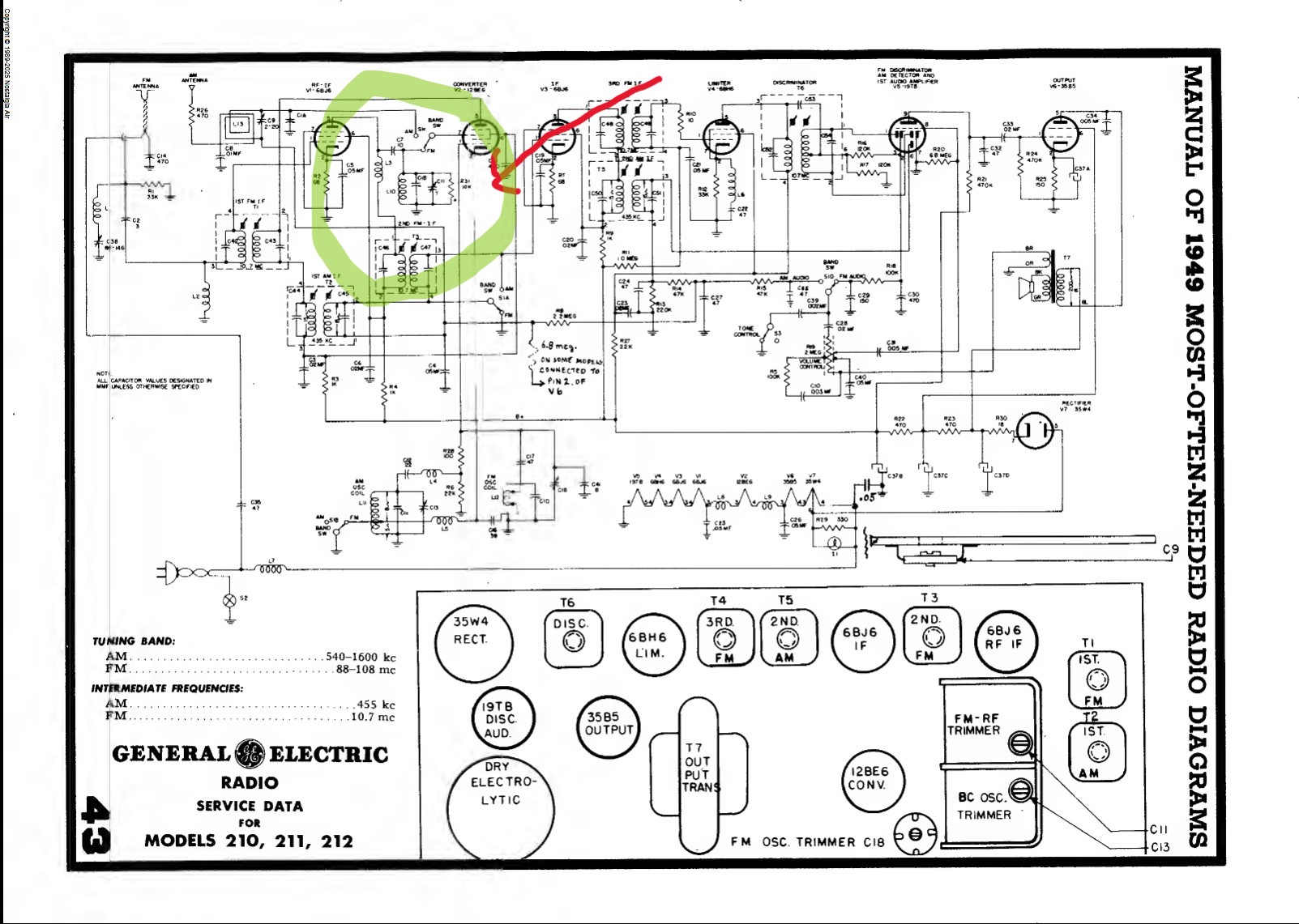
L10, C1B, R31, C11, and the band switch appear to be soldered at BOTH ends to ground! The band switch is connected via a copper strap to one end. I just can't believe that GE would have done this, or that it would have passed QC. MrFixr told me to look at the band switch  and I swear that I did the continuity checks.
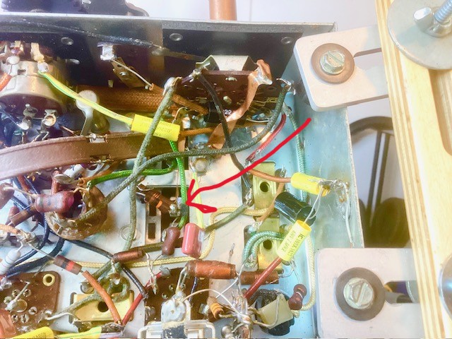
What do you think? I can separate the components, but is this how that circuit should be? My head aches!! Thanks all! Joe
Courage will follow when Faith takes the lead.
(This post was last modified: 08-10-2026, 06:10 PM by Joe Rossi.)
Posts: 5,656
Threads: 56
Joined: Sep 2008
City: Sandwick, BC, CA
The caps inside the AM IF transformers would be hard to measure as they are across the windings, you would have to remove them to measure, which means taking the transformers out, and apart. I'm pretty sure that one or more of tie mica caps in those transformers might be open if adjusting the slugs doesn't do anything to the gain. I have an older AM/FM radio that has the opposite problem, the AM side is fine, but the FM is deaf, only picks up the two strong local stations, and rather weakly, the tubes are fine, tested those, it could be the electrolytic for the ratio detector but maybe not, so on the shelf it sits.
Regards
Arran
(This post was last modified: 08-10-2026, 02:31 PM by Arran.)
Posts: 711
Threads: 46
Joined: Sep 2009
City: Lapeer, MI
State, Province, Country: USA
Thank you Arran. When I measured the IF cans, it was for the coil resistance. As such they were 15-16 ohms, schematic shows 15 ohms for their value. I'm going to button this one up and call it a day. I may come back to it in the winter and rip open the IF cans. For now, I have more radios to work on, including a Canadian Philco model 81 Transitone. Cheers, Joe
Courage will follow when Faith takes the lead.
Users browsing this thread: 1 Guest(s)
|
|
Recent Posts
|
|
Philco 71 Code 125
|
| Technically, that's C-. B- is chassis ground. The resistor between chassis ground and the HV center tap makes the HV c...MrFixr55 — 11:24 PM |
|
54C Cabinet Refinish
|
| hello Roy,
I’d follow Arran’s suggestion and use automotive gasket material, which I keep around for situations like th...radiorich — 10:22 PM |
|
Philco 71 Code 125
|
| This might be one of those cases where it's a ground to an AC voltage and B- to DC.RodB — 08:22 PM |
|
Philco 71 Code 125
|
| Really Rod? I know you would not steer me wrong but AI say this is a short circuit? What if I moved the 6 volt center ta...dconant — 06:40 PM |
|
54C Cabinet Refinish
|
| Roy;
Personally I would have left the asbestos alone if it were my set, but you can find a modern substitute that som...Arran — 04:51 PM |
|
Philco 71 Code 125
|
| Looks like that might be the B- buss, so that would be correct.RodB — 01:32 PM |
|
Philco 71 Code 125
|
| I noticed on the code 121 schematic the center tap for the 6 volt winding and hv winding are tied together. Is this corr...dconant — 12:16 PM |
|
Philco 45-6365 Universal IFT Instruction Manual
|
| The Philco Parts Catalog for 1942 shows it as usable for 175 kHz, 260 kHz, and 465 kHz. The instructions will show how t...DaleHCook — 11:19 AM |
|
Stromberg Carlson 1500 Squeal
|
| Hello Rob,
I agree with you—I have one here at my house that I need to check out. It’s way over-engineered just to make...radiorich — 11:05 AM |
|
My Atwater Kent 84
|
| Well getting around to restoring my AK84. Mike was a big part in me being able to snatch this one a few years ago. I won...462ron — 10:57 AM |
|
Who's Online
|
There are currently 1783 online users. [Complete List]
» 2 Member(s) | 1781 Guest(s)
|
|
|

|
 
|







