Welcome Guest! Be sure you know and follow the Phorum Rules before posting. Thank you and Enjoy! (January 12) x

Thread Closed
Thread Rating:
  • 0 Vote(s) - 0 Average
  • 1
  • 2
  • 3
  • 4
  • 5

37-620 Plate Resistor?
#1

Hi All,
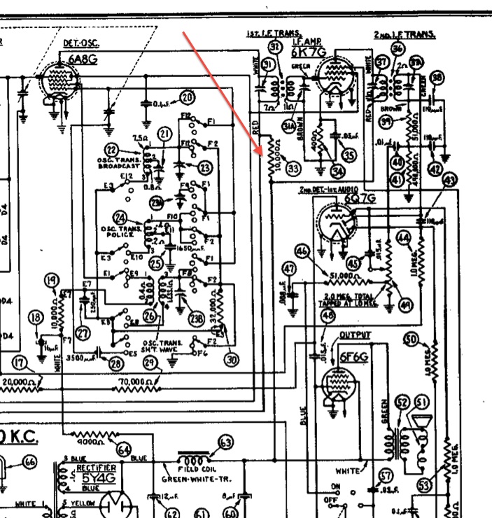
This is sort of a techy question but, as I work through the IF section on my 37-620 checking values, I see that resistor Part 33 is 10K on the schematic, but 1K on the parts list. Turns out it looks original and is in fact 1K (1.1K actually).

Looking at the socket voltages (haven’t ever been able to fire it up due to its poor condition) the plate of the first IF is 250V and the plate of the Det.Osc. is 245V. So 5V is dropped across Part 33. That’s only .5 ma. My theory is probably a little weak but that doesn’t seem like enough current to run both the 6A8 and the RF section 6K7. In fact it doesn’t seem like enough to run either tube alone. OK, so 1K is probably correct, the radio must have worked at some point. So anyway, why bother to put in a 1K at all? Seems like it would work fine without that resistor.

Anybody got any thoughts on this?
Tks,
Vic
   
   
#2

That resistor looks like a decoupling resistor, used to isolate the power supply of the IF stage from the converter and RF stages. Sometimes if B+ power is applied to all stages from the same source, you may get instability or oscillations due to the common power source. The resistor, together with a bypass cap serves to filter the supply and isolate the stages from each other preventing the problem.

Most likely, the 10K value on the schematic was a typo, all to common on the Philco schematics. The plates of the 6K7 and 6A8 probably draw about 10 mA total, so there would be a voltage drop of 10 volts or so across 1K which seems reasonable. A 10K would give 100V of drop which would clearly be excessive.
#3

When they install a resistor in the plate circuit of a tube a lot of it has to do with the potential between elements. Since this is used in the plate circuit of the 6A8 convertor tube I would replace it with one of an identical value, Philco was not in the habit of adding parts without a reason.
Regards
Arran
#4

Thanks for the replies! I had no intention of leaving out something just because I don’t understand its function. It was the apparent typo on the print that aroused my curiosity. What keeps me interested in the hobby is the challenge of getting these sets to work again. And it sure helps me when I get an understanding of why they are designed as they are. Thanks again and regards.
Vic
#5

Agree, and beware if you are measuring voltages with a modern digit al mewter or even a VTVM, either of which will present little or no load. Ancient meters presented a significant load and so readings were guestimates at best.

Replace all the little carbon resistors along with the electrolytic and tubular capacitors.

Makes a huge difference in the end for safety, reliability, and longevity.

Up to you!


Users browsing this thread: 1 Guest(s)
[-]
Recent Posts
Model 70 Cabinet Trim
Hello musar, First all welcome to the forum and yes that is true that steve stopped making trim . Sincerely Richar...radiorich — 12:13 AM
Model 70 Cabinet Trim
I have recently come into possession of a Model 70.  The trim around the base needs to be replaced.  If this were years ...musar — 12:07 AM
philcorepairbench.com - shadow-meter
Anyone know of a way to recover these files from the repair bench? Thanks. fenbach — 11:16 PM
Philco model 38 code 121 not receiving signal.
That's true. Of course If I were to get a vtvm I'd probably have to sink money in to it to get it working right. Probabl...Stormlord5500 — 08:44 PM
Philco model 38 code 121 not receiving signal.
A DMM is good enough. One rarely has to measure indictance, but if you do, short of getting a serious LCR meter (I hav...morzh — 07:35 PM
Testing a speaker and output transformer Trutone A2-G
You guy's are right on. I found a broken wire on the speaker plug that I replaced and all is well now. Have better volu...murf — 03:43 PM
Philco model 38 code 121 not receiving signal.
I need to get a vtvm. I think that little component tester is just more accurate. Plus it shows the inductance which is ...Stormlord5500 — 03:07 PM
Philco model 38 code 121 not receiving signal.
I use a pair of Mastercraft brand DMMs from Canadian Tire, from what I read most of those DMMs use the same main chip re...Arran — 02:36 PM
Philco model 38 code 121 not receiving signal.
Thank you sir. Yes I feel good and also relieved because this one's been weighing on me a bit.Stormlord5500 — 11:18 AM
Philco model 38 code 121 not receiving signal.
It feels good don't it? Good luck on the rest.Paul Philco322 — 11:06 AM

[-]
Who's Online
There are currently no members online.

>