Welcome Guest! Be sure you know and follow the Phorum Rules before posting. Thank you and Enjoy! (January 12) x

Thread Closed
Thread Rating:
  • 0 Vote(s) - 0 Average
  • 1
  • 2
  • 3
  • 4
  • 5

cap questions on model 89 (version 6 schematic)
#1

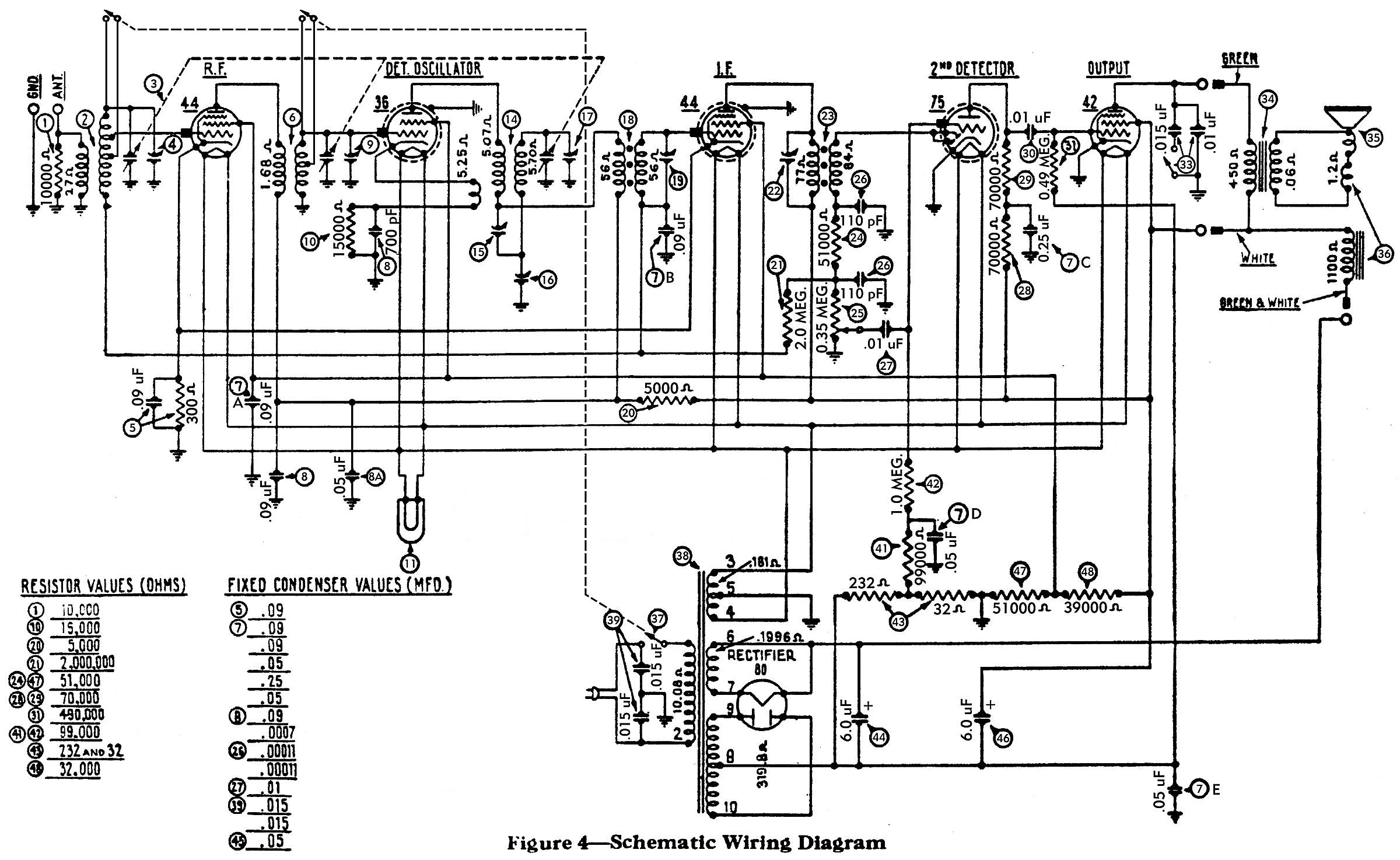
I really could use another pair of eyes and some good advice here from those more experienced than I. I'm trying to replace the caps in the #7 Filter condenser bank. There are 5 caps in that "bank", each are number 7 on the attached schematic. I'm trying to find where the .09 mfd's go? It almost looks like two of them go to the #44 RF tube on the front corner of the chassis. The other end goes to ground, of course.

The other question I have concerns the #5 bakelite block. There's a .09 mfd cap in the block along with a 300 ohm resistor. Should there be a wire going from one terminal of the block to the #41 (99,000 ohm) resistor? There are two wires coming from the variable capacitor going to the ground terminal on the bakelite block. Is that correct? Also does one wire from this block go to the antenna coil?

I'm sure to most of you, these will all appear to be obvious. I just want to verify that what I'm doing is correct. You can never be too sure! Icon_smile Thanks in advance.


Greg V.
West Bend, WI
Member WARCI.org
#2

It looks like 1 .09 goes to the grid of both 44's and the 36 the other .09 goes to coil #18 and the ant coil
#3

The #5 block is in series to ground from pin 4 of both 44's. They are probably just using the ground conection on the block because it was the closest/convenient ground.
#4

The cap going to resistor 41 should be a .05
#5

Thanks, tab. My chassis was a mess... someone, sometime long, long ago added and replaced a bunch of stuff and so much of what was reconnected was soldered onto the wrong lugs. I'm going through the schematic with a highlighter pen trying to trace out each and every wire / connection / component. A daunting process. The .05 cap between the 41 & 42 resistors was an easy one to find. But on my chassis, there was a wire going from the #5 block to the 41 resistor. I'm thinking it doesn't belong there.

Greg V.
West Bend, WI
Member WARCI.org


Users browsing this thread: 1 Guest(s)
[-]
Recent Posts
The list of my radio & TV collection!
A little light Saturday positive about our hobby in our feed... My new every Saturday video about antique radio equipme...RadioSvit — 02:12 PM
Model 70 Cabinet Trim
musar , Well if you have any more questions feel free to post away . Sincerely Richardradiorich — 08:56 PM
Model 70 Cabinet Trim
Although I have not made any cabinets or cabinet parts for a couple of years, I still have some parts left over, includi...Steve Davis — 06:26 PM
philcorepairbench.com - shadow-meter
Thanks Ron.fenbach — 02:43 PM
Model 70 Cabinet Trim
Thank you, Gary. Before making my original post, I had clicked on "Steve Davis Cabinets" only to find that it...musar — 02:25 PM
philco predicta
Welcome to the Phorum, cgl18! I am not your resource for television repair, but lots of friendly help is available here...GarySP — 02:12 PM
Model 70 Cabinet Trim
Welcome to the Phorum, musar! You can send Steve Davis a private message (PM). The site is at the top of the Home page...GarySP — 02:09 PM
Model 70 Cabinet Trim
How do I contact him? The only contact information for him I could find when searching online was a telephone number th...musar — 10:38 AM
philco predicta
Hello, good afternoon, I would like to ask what the possible problem could be if I don't have an image on the screen. I ...cgl18 — 10:19 AM
Philco model 38 code 121 not receiving signal.
So one last question before I finish this radio. Regarding the speaker and output transformer. I salvaged the original o...Stormlord5500 — 09:31 AM

[-]
Who's Online
There are currently 1249 online users. [Complete List]
» 1 Member(s) | 1248 Guest(s)
Avatar

>