



01-20-2019, 11:58 PM
More analysis theory. Hopefully this is easier to understand
After redrawing the circuit again. It looks like two functions are going on.
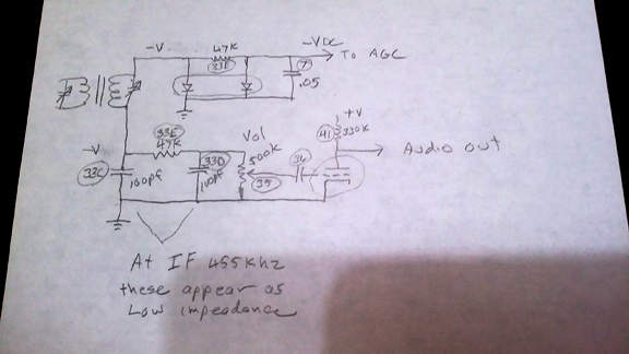
In my drawing I have the resistor #33e as 47k which is wrong it should have been #34 at 2.2meg.
On the diodes side of the transformer any positive voltage is shorted to ground which pushes all the negitive voltage to the detector side. This charges the caps 33C and 33D which act as filters but only at IF speed. There voltage discharges fast enough to follow the audio voltage.
While the caps 33C and D hold their charge and the IF changes polarity the voltage on the other side of the transformer sits on top of voltage of the caps which is now doubled and stored in C7 for use to control the gain of the IF stages.
Its interesting to note that both sides of the transformer are driving the two circuits negative which reinforce each other as voltage doublers.
All this still doesn't help me to figure out how this worked without the ground on the volume pot.
After redrawing the circuit again. It looks like two functions are going on.
In my drawing I have the resistor #33e as 47k which is wrong it should have been #34 at 2.2meg.
On the diodes side of the transformer any positive voltage is shorted to ground which pushes all the negitive voltage to the detector side. This charges the caps 33C and 33D which act as filters but only at IF speed. There voltage discharges fast enough to follow the audio voltage.
While the caps 33C and D hold their charge and the IF changes polarity the voltage on the other side of the transformer sits on top of voltage of the caps which is now doubled and stored in C7 for use to control the gain of the IF stages.
Its interesting to note that both sides of the transformer are driving the two circuits negative which reinforce each other as voltage doublers.
All this still doesn't help me to figure out how this worked without the ground on the volume pot.
!!!!!!!!!!!!!!!!!!!RESISTANCE IS FUTILE!!!!!!!!!!!!!!!!!!!!!!
/\/\/\/\/\/\/\/\/\
[Image: http://philcoradio.com/phorum/images/smi...on_eek.gif] Chris


