01-02-2022, 01:21 PM
I feel like the ghost of Christmas past, Terry....even though the other power supply wasn't done around Christmastime.
Here's the full schematic which may be easier to read than the screen capture I posted:
http://www.nostalgiaair.org/PagesByModel...017167.pdf
I thank you very kindly for the ideas to modify the power supply design to accommodate the vibrator supply, and may have to go that route, but I'd like to consider this first...
After the success with the last power supply in 2017, and while everything was still available. I purchased a second set of components figuring I'd be able to use it for another farm set. So basically I have everything here to build the original one again and am wondering if there's a way to use that on this Silvertone by eliminating that neat little metal box that contains the vibrator supply?
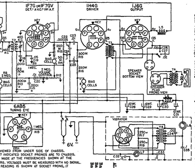
Here's a crop of that section of the schematic:

I'm only seeing 3 wires coming out of that metal box. One is grounding the box to the Negative - cable, another is going to the off/on switch, and the third going to the positive side of the 12 MFD electrolytic and to L6 (and points beyond). In theory it looks simple enough to eliminate but of course may not be.
So to pose an overly simple question to a complicated problem, (but one that would make it a whole lot easier for me to understand), with the box eliminated, where is the best place to connect A + & A - and B + and B - using your original power supply?
I'll wait for you to stop laughing!
Here's the full schematic which may be easier to read than the screen capture I posted:
http://www.nostalgiaair.org/PagesByModel...017167.pdf
I thank you very kindly for the ideas to modify the power supply design to accommodate the vibrator supply, and may have to go that route, but I'd like to consider this first...
After the success with the last power supply in 2017, and while everything was still available. I purchased a second set of components figuring I'd be able to use it for another farm set. So basically I have everything here to build the original one again and am wondering if there's a way to use that on this Silvertone by eliminating that neat little metal box that contains the vibrator supply?
Here's a crop of that section of the schematic:
I'm only seeing 3 wires coming out of that metal box. One is grounding the box to the Negative - cable, another is going to the off/on switch, and the third going to the positive side of the 12 MFD electrolytic and to L6 (and points beyond). In theory it looks simple enough to eliminate but of course may not be.
So to pose an overly simple question to a complicated problem, (but one that would make it a whole lot easier for me to understand), with the box eliminated, where is the best place to connect A + & A - and B + and B - using your original power supply?
I'll wait for you to stop laughing!
Greg V.
West Bend, WI
Member WARCI.org


![[-] [-]](https://philcoradio.com/phorum/images/bootbb/collapse.png)


