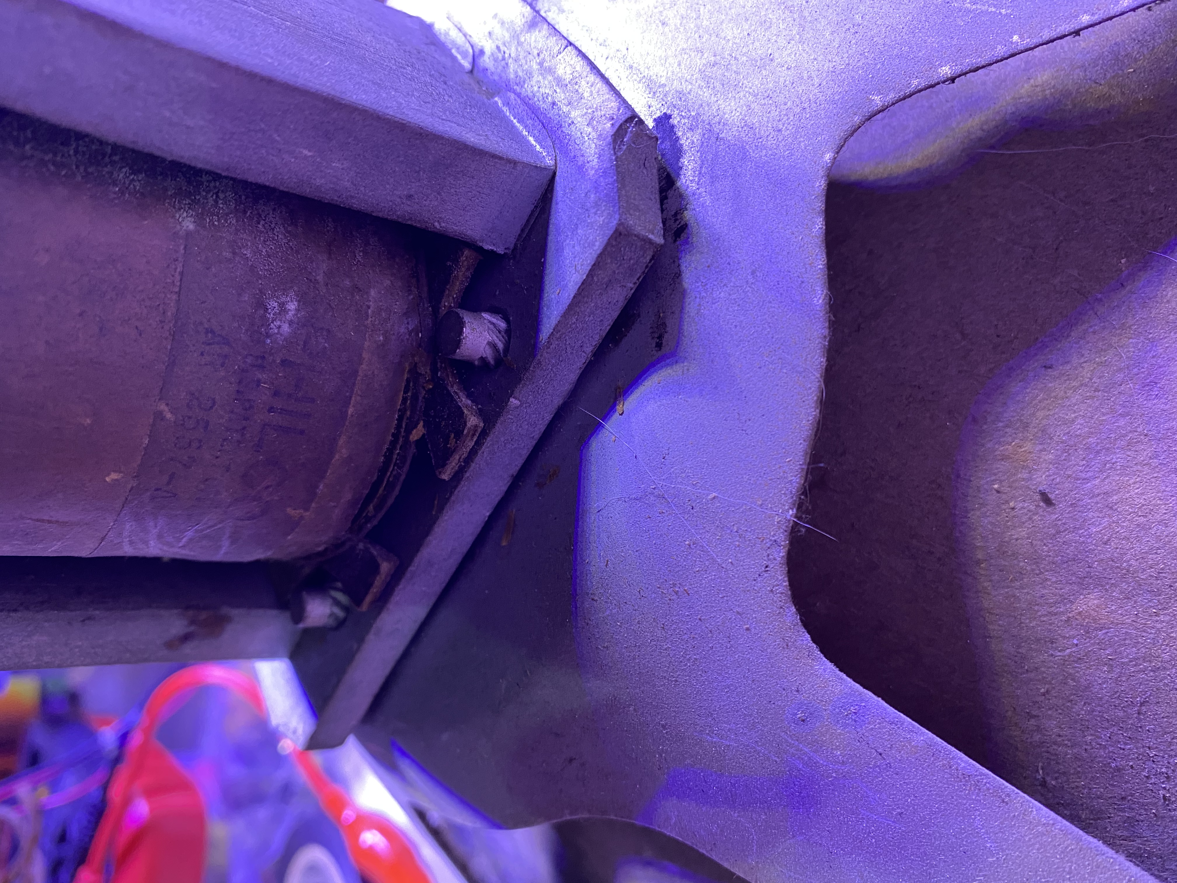
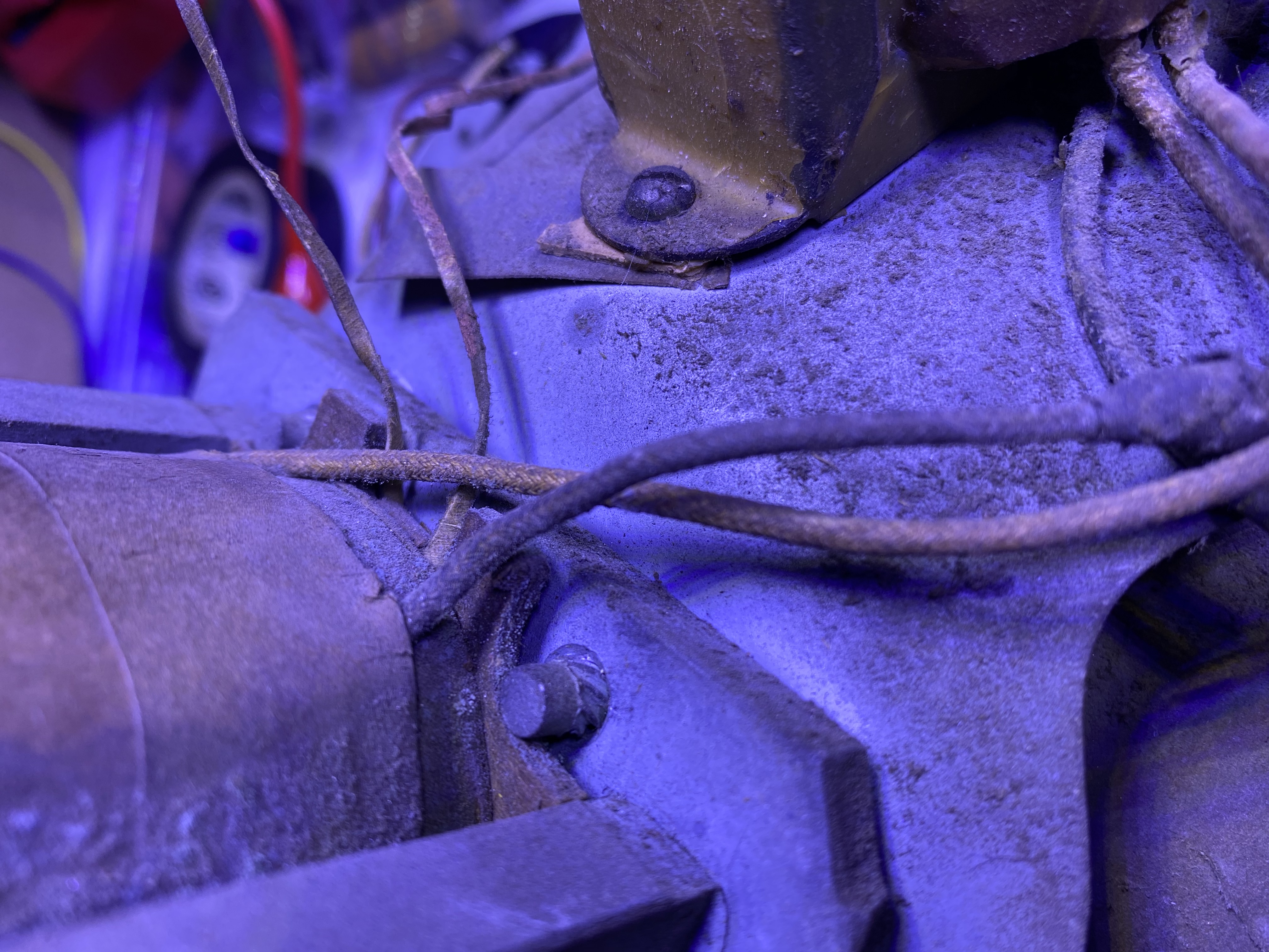
02-13-2022, 05:15 PM
Greetings all- I went silent on this as I’ve worked in bits and pieces over the past few months and I now have a working set.
The cap in question was one half of the power filter can, so either the other side hadn’t died yet or the repair person didn’t think it was important.
Anyway, after many replacements and parts-wrangling, the radio is working( for what poor reception I get here even with modern equipment). And I’m down to shifting bits and pieces prior to remounting in the cabinet(another thread pending in cabinet restoration coming soon)
I don’t have any GOOD reason to dump the field coil on the speaker and replace it with a “rigged choke” as it is working surprisingly well. I’d also like to avoid changing caps to support a large resistor. This is not an easy chassis to fiddle in.
I just won’t have space in the cabinet to keep the coil on the completely trashed speaker. 80+ years of bad storage, pets, and kids have destroyed the cone. So I want to keep the original output xformer(don’t ask. Please) and the field coil/choke. Just mounted elsewhere.
I cannot, for the life of me, figure out how these strange smooth-headed bolts are keeping this thing in short of “they just pounded them in”
So... do I just pound them back out, in reverse?
Check out these weird twisty attachment things at the corners. The other side is a smooth round bolt head. Nothing to turn.
Before I proceed on a “gosh, you’re kinda not all the bright, are ya?” course of action... is there something about these I’m just not seeing that should be obvious?
Knows enough to be dangerous, occasionally successful, rarely correct.


![[-] [-]](https://philcoradio.com/phorum/images/bootbb/collapse.png)


