05-30-2023, 09:00 PM
Hi Dale,
No, I have not repaired one of these but since the speaker on this unit is attached to the amplifier chassis, I would suspect that the leads are soldered to the terminals, and those terminals are likely only for the voice coil. The earlier models R32, R52, etc. used what looks like a 4 pin Jones connector., as these speakers were not connected to the amp chassis. My GE S-22A (RCA R7A) has a rather similar speaker.
I think that these radios were designed and built just before the acquisition of Victor by RCA. The amplifier is rather similar in layout and circuit to the Radiola 80, which (I believe) is the first RCA radio built in the Camden, NJ Victor plant instead of being built by GE or Westinghouse.
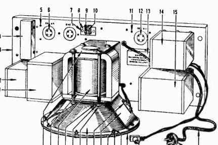
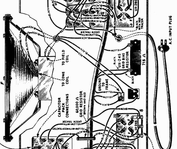
Attached below are pictorials of the Victor R-35 and the Radiola 80, bearing out the likelihood that the speaker connection is soldered at 2 terminals on a strip for the voice coil and the field coil leads being pigtails directly from the coil.


From what I can discern, the only difference between the Radiola 80 and the Victor R35Amp Chassis are the method of connecting the radio chassis and the fact that the Field coil is in the B return side on the Radiola 80 as opposed to being on the B+ side on the Victor.
In my book, this is a cool radio, as it was Victor's entry into building their own radios (they previously bought Radiola 16s, 17s or 18s from RCA.
No, I have not repaired one of these but since the speaker on this unit is attached to the amplifier chassis, I would suspect that the leads are soldered to the terminals, and those terminals are likely only for the voice coil. The earlier models R32, R52, etc. used what looks like a 4 pin Jones connector., as these speakers were not connected to the amp chassis. My GE S-22A (RCA R7A) has a rather similar speaker.
I think that these radios were designed and built just before the acquisition of Victor by RCA. The amplifier is rather similar in layout and circuit to the Radiola 80, which (I believe) is the first RCA radio built in the Camden, NJ Victor plant instead of being built by GE or Westinghouse.
Attached below are pictorials of the Victor R-35 and the Radiola 80, bearing out the likelihood that the speaker connection is soldered at 2 terminals on a strip for the voice coil and the field coil leads being pigtails directly from the coil.
From what I can discern, the only difference between the Radiola 80 and the Victor R35Amp Chassis are the method of connecting the radio chassis and the fact that the Field coil is in the B return side on the Radiola 80 as opposed to being on the B+ side on the Victor.
In my book, this is a cool radio, as it was Victor's entry into building their own radios (they previously bought Radiola 16s, 17s or 18s from RCA.
"Do Justly, love Mercy and walk humbly with your God"- Micah 6:8
"Let us begin to do good"- St. Francis
Best Regards,
MrFixr55


![[-] [-]](https://philcoradio.com/phorum/images/bootbb/collapse.png)


