11-11-2023, 12:13 AM
Thanks for that, Joe. No mine has no eye tube.
Well here's an interesting plot twist. I finally got to hear the radio play tonight, but only by changing ALL of the tubes!
Here's what happened. When I got this radio, I searched for mini console Baby Grand, and found a thread about it over on ARF:
Ah ha! I now had the information I needed to find a schematic! It was either the Warwick 5 (or 6) tube chassis schematic, or the model 510C chassis. I printed them out and found that the chassis configuration (tube layout) matched. Bingo!
Upon removing the chassis, I found that the two large tubes were actually broken. Half of the glass was missing. And the other three rattled like maracas. So I removed them, and knowing they all were bad, put them aside and found the correct (or what i THOUGHT were correct) tubes: the 80, 42, 75, 6D6, 6A7.
So that's when I noticed the discrepancy between the volume control layout. I got NO sound whatsoever when I had it wired per the 5 & 6 tube chassis schematic, so I rewired it to the 510C chassis layout. STILL no sound. And voltages were way high. I began to suspect the power transformer was bad so I did some testing. With all of the tubes out, under power I got 2.5 volts across the heater pins on each tube. That made sense why I was getting no sound.
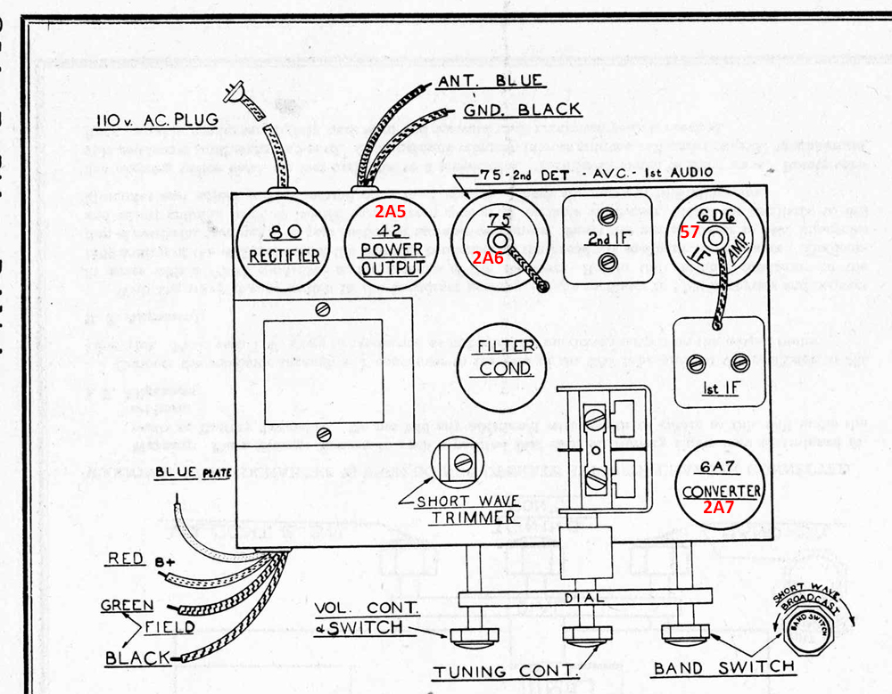
So I started digging around for a different power transformer when the light bulb went on. Could it be that this thing was wired for 2.5 volt tubes? I went back and looked at the tubes I pulled out and found a 2A5, 2A6, 2A7 and a 57. So I found and tested each of those from my tube stash, figured out which corresponded to the 6.3 volt tubes I had installed, replaced each, powered it up and it actually played well!
So here is the tube layout with the 2.5 volt tubes listed in red:

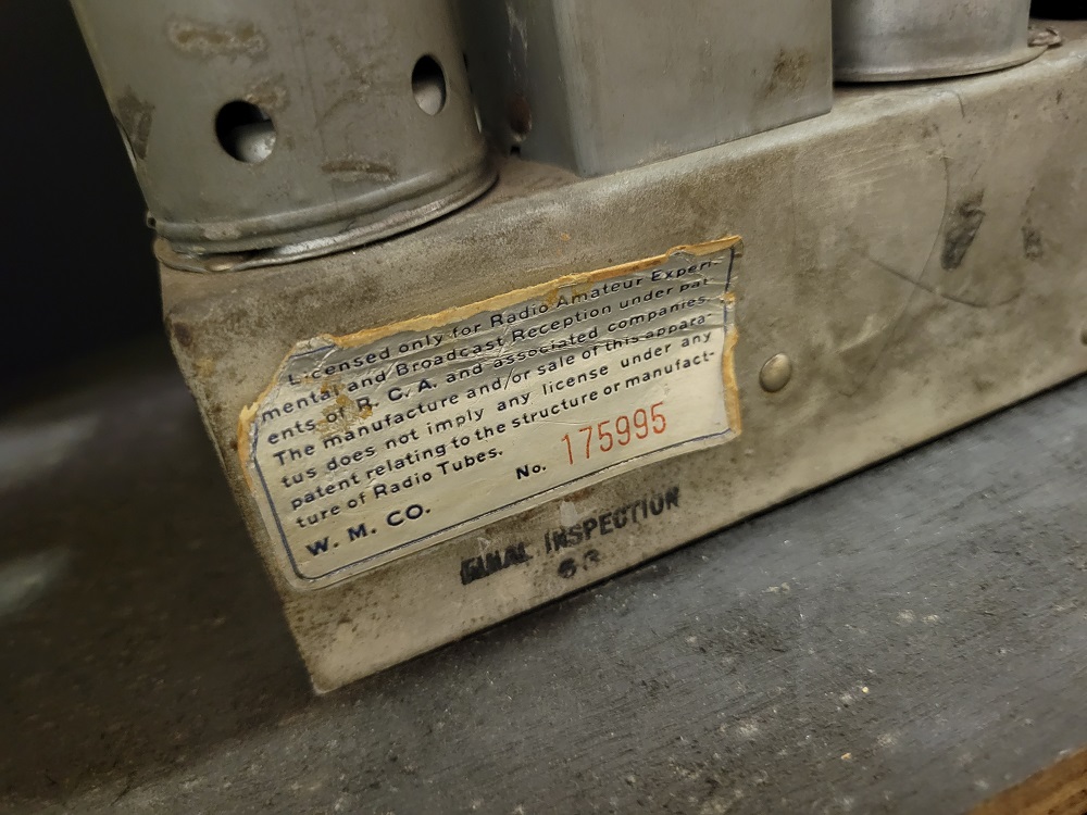
And here's the label on the back of the chassis:

Now my only concern is that some of the resistor values are different from the Warwick 510C chassis to whatever chassis I have now. Can anyone locate a Warwick schematic with the same chassis layout and 2.5 volt tube configuration?
Upon closer inspection it appears the transformer MAY have been replaced once in the past, as the screws and nuts holding it to the chassis are newer and shiny. So maybe the person who changed it only had a transformer for 2.5 filament voltage and just subbed the tubes on his own. It's a mystery!
Well here's an interesting plot twist. I finally got to hear the radio play tonight, but only by changing ALL of the tubes!
Here's what happened. When I got this radio, I searched for mini console Baby Grand, and found a thread about it over on ARF:
Ah ha! I now had the information I needed to find a schematic! It was either the Warwick 5 (or 6) tube chassis schematic, or the model 510C chassis. I printed them out and found that the chassis configuration (tube layout) matched. Bingo!
Upon removing the chassis, I found that the two large tubes were actually broken. Half of the glass was missing. And the other three rattled like maracas. So I removed them, and knowing they all were bad, put them aside and found the correct (or what i THOUGHT were correct) tubes: the 80, 42, 75, 6D6, 6A7.
So that's when I noticed the discrepancy between the volume control layout. I got NO sound whatsoever when I had it wired per the 5 & 6 tube chassis schematic, so I rewired it to the 510C chassis layout. STILL no sound. And voltages were way high. I began to suspect the power transformer was bad so I did some testing. With all of the tubes out, under power I got 2.5 volts across the heater pins on each tube. That made sense why I was getting no sound.
So I started digging around for a different power transformer when the light bulb went on. Could it be that this thing was wired for 2.5 volt tubes? I went back and looked at the tubes I pulled out and found a 2A5, 2A6, 2A7 and a 57. So I found and tested each of those from my tube stash, figured out which corresponded to the 6.3 volt tubes I had installed, replaced each, powered it up and it actually played well!
So here is the tube layout with the 2.5 volt tubes listed in red:
And here's the label on the back of the chassis:
Now my only concern is that some of the resistor values are different from the Warwick 510C chassis to whatever chassis I have now. Can anyone locate a Warwick schematic with the same chassis layout and 2.5 volt tube configuration?
Upon closer inspection it appears the transformer MAY have been replaced once in the past, as the screws and nuts holding it to the chassis are newer and shiny. So maybe the person who changed it only had a transformer for 2.5 filament voltage and just subbed the tubes on his own. It's a mystery!
Greg V.
West Bend, WI
Member WARCI.org


![[-] [-]](https://philcoradio.com/phorum/images/bootbb/collapse.png)


