



12-01-2025, 10:52 PM
Hi Hamilton,
First off, this is a rather high-end radio for its time and certainly worthwhile repairing. You will have a nice sounding radio when done. Consider adding a Radio - Aux Switch when done, so you can pipe big band music or old time radio directly int the set.
This is more complex than the average radio, and pre-WWII radios have some interesting features on power supplies that post WWII radios don't have, but do not be discouraged about not being able to read schematics, first off, we will be very happy to help you! Second off, google reading schematics and you should also find help.
You already have some skills as you found the section of Cap #89 that connects to the screen grid of the 1st Audio Amp tube.
Below is a schematic representation of a vacuum tube. The elements of a vacuum tube are as follows (Pentode shown, there are diodes, triodes and tetrodes and special types also):
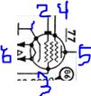
1. Cathode (Emits Electrons)
2. Control Grid (Input to the tube, controls the flow of electrons from the cathode to the plate, and therefore the output current at the plate)
3. Screen Grid (helps accelerate the electrons to the plate and helps reduce inter-electrode capacitance
4. Suppressor Grid (Reduces "secondary emissions")
5. Plate (The output of the tube)
6. Heater (heats cathode to emit electrons)
The following is a link to the 1933 version of the RCA Receiving Tube manual. Reading the first section will explain how a Vacuum Tube functions:
RCA-Radiotron-manual-R-10-1933-87-pages.pdf
Resistors look like this on a schematic:
-VVVVVV-
Capacitors look like this:
--||--
Filter Chokes look like this:

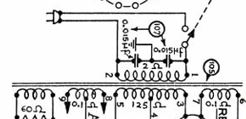
Transformers look like this (This example is a power transformer):
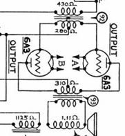
Here is how interstage and output transformers and a speaker connect to the Power Output tubes of a radio.
I numbered several connections on the following cutout of the schematic of this set, which may help you find some waypoints:
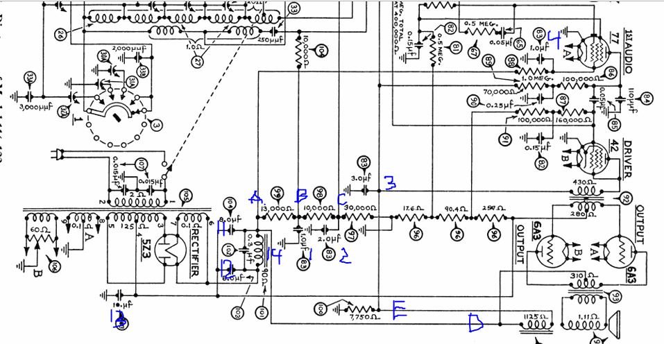
Resistors 99, 98 and 97 are connected in series (end to end) and form a "voltage divider" between the output of the power supply and ground.
Point A is the junction between one leg of Resistor #99, the output of the power supply choke #101, the lead to the speaker field coil and audio output transformer center tap.
Point B is the junction of the other leg of Resistor #99 and one leg of resistor #98, one leg of resistor 104 and a 1.0 uF Cap (Labeled 1) that is part of Cap # 89.
Point C is the junction of the other leg of Resistor #98, one leg of Resistor #97, a wire that leads to the screen grids of several IF, RF and converter tubes, and to a 2.0 uF Cap (Labeled 2) that is part of Cap #89.
The other leg of Resistor #97 connects to Chassis Ground (B-, C+), completing this voltage divider
Point D is the connection to one leg of the speaker field coil (an electromagnet) and the center tap of the primary of the Audio Output Transformer (The 2 "ends" of the primary connect to the plates of the 2 Audio Output tubes). Point D connects to Point A. The field coil and resistor #100 comprise another voltage divider.
Point E is the junction of the other leg of the speaker's field coil, one leg of a 7,750 Ohm Resistor #100, the primary of the interstage transformer, other points and a 3.0 uF cap, (Labeled 3) of Cap #89. The other leg of the 7,750 Ohm Resistor #100 connects to chassis ground, completing that voltage divider.
Please note that almost all electrolytics used in power supplies are polarized. For Cap #89, the negative terminals of all caps that comprise Cap #89 all go to Chassis Ground. Please note that the Chassis Ground is not the most negative part of the power supply; the center tap of the HV secondary of the Power Supply is. In this configuration, "C-" voltage comes from this point.
Please note that the negative terminals of the main filter caps, labeled 103, 104 and 104 (not a duplicate) do not go to chassis ground, they go to the center tap of the HV secondary, the most negative point on the schematic.
Hope this helps.
First off, this is a rather high-end radio for its time and certainly worthwhile repairing. You will have a nice sounding radio when done. Consider adding a Radio - Aux Switch when done, so you can pipe big band music or old time radio directly int the set.
This is more complex than the average radio, and pre-WWII radios have some interesting features on power supplies that post WWII radios don't have, but do not be discouraged about not being able to read schematics, first off, we will be very happy to help you! Second off, google reading schematics and you should also find help.
You already have some skills as you found the section of Cap #89 that connects to the screen grid of the 1st Audio Amp tube.
Below is a schematic representation of a vacuum tube. The elements of a vacuum tube are as follows (Pentode shown, there are diodes, triodes and tetrodes and special types also):
1. Cathode (Emits Electrons)
2. Control Grid (Input to the tube, controls the flow of electrons from the cathode to the plate, and therefore the output current at the plate)
3. Screen Grid (helps accelerate the electrons to the plate and helps reduce inter-electrode capacitance
4. Suppressor Grid (Reduces "secondary emissions")
5. Plate (The output of the tube)
6. Heater (heats cathode to emit electrons)
The following is a link to the 1933 version of the RCA Receiving Tube manual. Reading the first section will explain how a Vacuum Tube functions:
RCA-Radiotron-manual-R-10-1933-87-pages.pdf
Resistors look like this on a schematic:
-VVVVVV-
Capacitors look like this:
--||--
Filter Chokes look like this:
Transformers look like this (This example is a power transformer):
Here is how interstage and output transformers and a speaker connect to the Power Output tubes of a radio.
I numbered several connections on the following cutout of the schematic of this set, which may help you find some waypoints:
Resistors 99, 98 and 97 are connected in series (end to end) and form a "voltage divider" between the output of the power supply and ground.
Point A is the junction between one leg of Resistor #99, the output of the power supply choke #101, the lead to the speaker field coil and audio output transformer center tap.
Point B is the junction of the other leg of Resistor #99 and one leg of resistor #98, one leg of resistor 104 and a 1.0 uF Cap (Labeled 1) that is part of Cap # 89.
Point C is the junction of the other leg of Resistor #98, one leg of Resistor #97, a wire that leads to the screen grids of several IF, RF and converter tubes, and to a 2.0 uF Cap (Labeled 2) that is part of Cap #89.
The other leg of Resistor #97 connects to Chassis Ground (B-, C+), completing this voltage divider
Point D is the connection to one leg of the speaker field coil (an electromagnet) and the center tap of the primary of the Audio Output Transformer (The 2 "ends" of the primary connect to the plates of the 2 Audio Output tubes). Point D connects to Point A. The field coil and resistor #100 comprise another voltage divider.
Point E is the junction of the other leg of the speaker's field coil, one leg of a 7,750 Ohm Resistor #100, the primary of the interstage transformer, other points and a 3.0 uF cap, (Labeled 3) of Cap #89. The other leg of the 7,750 Ohm Resistor #100 connects to chassis ground, completing that voltage divider.
Please note that almost all electrolytics used in power supplies are polarized. For Cap #89, the negative terminals of all caps that comprise Cap #89 all go to Chassis Ground. Please note that the Chassis Ground is not the most negative part of the power supply; the center tap of the HV secondary of the Power Supply is. In this configuration, "C-" voltage comes from this point.
Please note that the negative terminals of the main filter caps, labeled 103, 104 and 104 (not a duplicate) do not go to chassis ground, they go to the center tap of the HV secondary, the most negative point on the schematic.
Hope this helps.
"Do Justly, love Mercy and walk humbly with your God"- Micah 6:8
"Let us begin to do good"- St. Francis
Best Regards,
MrFixr55


