



12-21-2025, 10:31 PM
Another thing I have noticed: this radio is a bit different from the schematic.
For instance, 1st and 2nd IFs have some large resistors to GND from their pins 6 (SG) whereas they are only supposed to have 680 Ohms pullups to the Plates' Positive bus. They seem to be in 22K or so range.
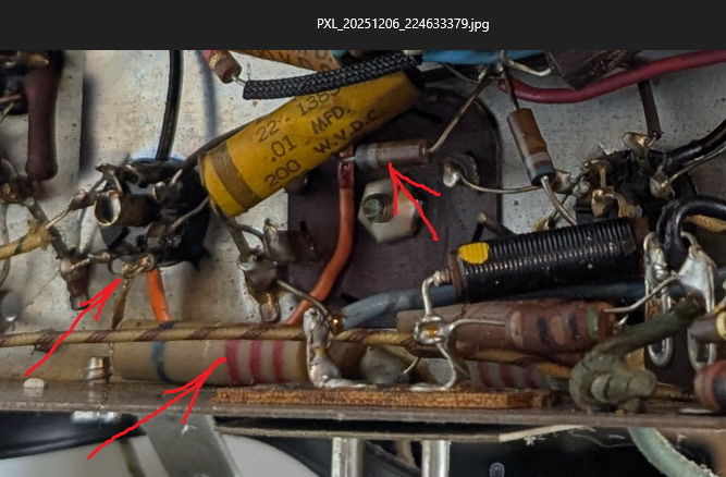
(all points of interest are marked with red arrows)
You can seer that the pin 6 of this 12BA6 (left arrow) connects with the orange wire to the 680 Ohm small resistor (right arrow). As it should.
But also that same pin is connected to what seems to be 22K large resistor (middle arrow) the other lead of which goes to GND.
You could also see another resistor like this one to the right (for the other 12BA6 tube).
The resistors are a large ceramic kind; I suspect at least 1W rated.
I wonder if the SG voltage on these was a bit high and they used these to lower it just a bit.
The soldering seemed factory professional, so I do not doubt this is not a mod/repair.
For instance, 1st and 2nd IFs have some large resistors to GND from their pins 6 (SG) whereas they are only supposed to have 680 Ohms pullups to the Plates' Positive bus. They seem to be in 22K or so range.
(all points of interest are marked with red arrows)
You can seer that the pin 6 of this 12BA6 (left arrow) connects with the orange wire to the 680 Ohm small resistor (right arrow). As it should.
But also that same pin is connected to what seems to be 22K large resistor (middle arrow) the other lead of which goes to GND.
You could also see another resistor like this one to the right (for the other 12BA6 tube).
The resistors are a large ceramic kind; I suspect at least 1W rated.
I wonder if the SG voltage on these was a bit high and they used these to lower it just a bit.
The soldering seemed factory professional, so I do not doubt this is not a mod/repair.
People who do not drink, do not smoke, do not eat red meat will one day feel really stupid lying there and dying from nothing.


