



02-15-2026, 09:43 AM
I've gone for a change in philosophy. I thought for some time about Mike's concerns and MrFixr's input about the flags. And, late last night, it dawned on me. I need to think beyond the PCB. That is, I can reduce all of this to a single disc if I mount the capacitors up and off of the PCB. In doing so, I can reduce their footprints down to only the minimum size needed for their through-hole leads.
I recreated the design with these reduced footprints. Even so, I've got a very small amount of real estate for three capacitors. Let me explain.
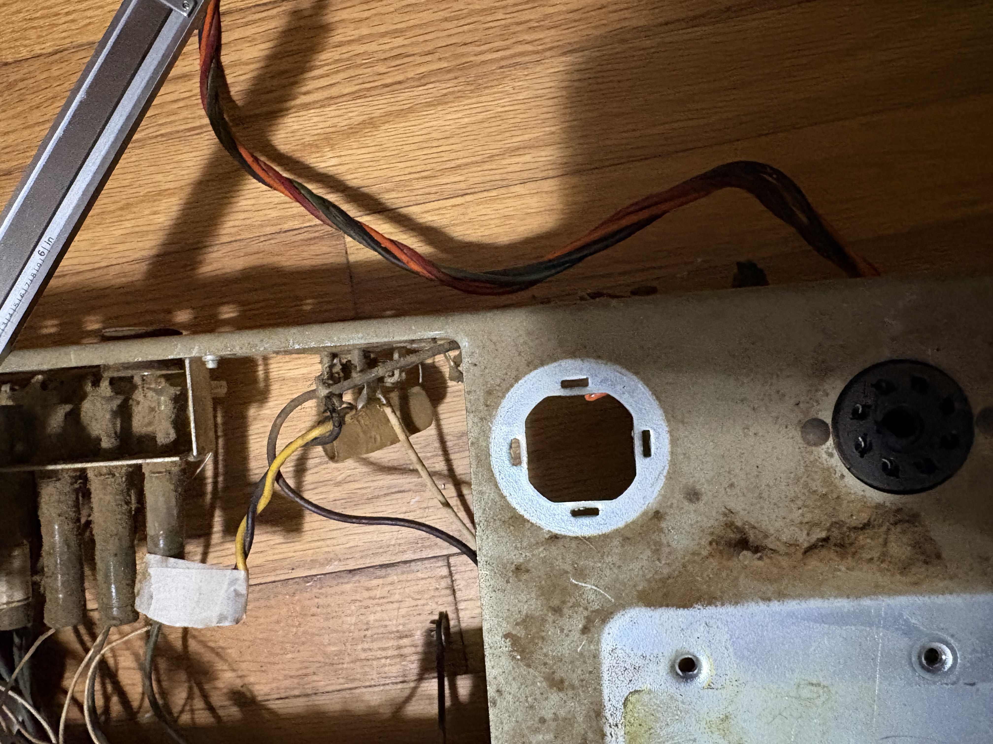
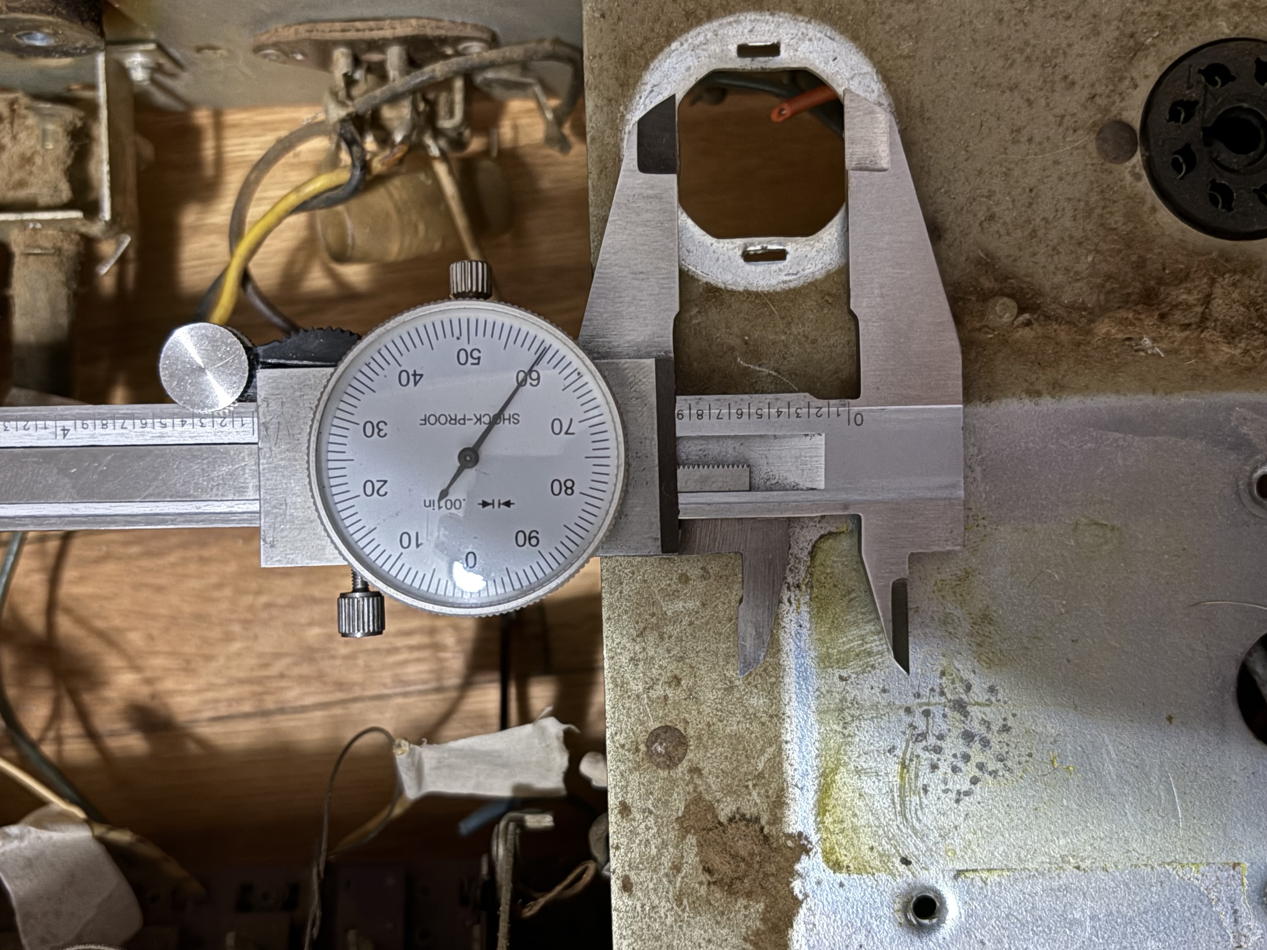
The solder lugs, twist lock lugs, and capacitors are through-hole mounted. Although the diameter of the capacitor I am replacing is 1.46", I need to fit all of my connectors within this 0.86" cutout on the chassis so that nothing with a potential different than the common negative will make contact with the chassis when the PCB is mounted. This is the same constraint I had when designing the twist-lock capacitor for my 46-480 last year, but it's an even taller order in this case with three capacitors. Basically, everything except for the twist-lock connectors and possibly any other common neutral connections needs to fit within that cutout. In addition, I need to maintain minimum clearance between any components and the outline of this cutout on the chassis.
With this in mind, I reduced the two schematics into one.
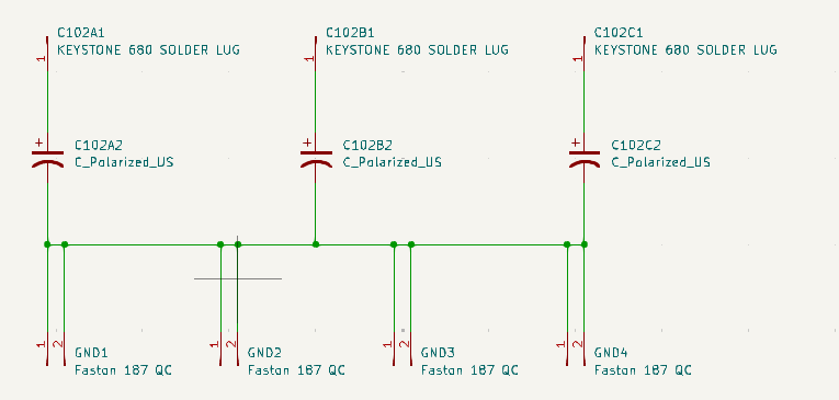
I then annotated the schematic, edited the footprints to reduce their size, and then paired the new footprints to their respective schematic symbols. Finally, I created the layout. In a pink or peach color (used to represent the bottom silkscreen layer), you'll see that I added the outline of the cutout on the chassis so that I could use it for measuring clearances.
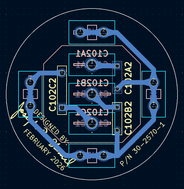
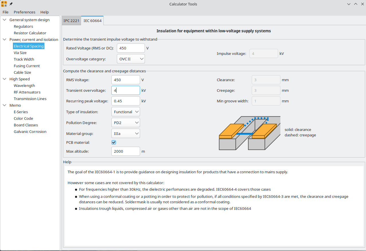
I found that I had enough space to beef up the traces to a full millimeter. I also have enough space to establish minimum creepage and clearance distances of greater than or equal to 3mm (as measured from the edges of any two adjaent surfaces or solder pads; the centerlines are spaced even further), which satisfies the IEC 60664-1 calculations (reinserting because I was actually able to satisfy even more aggressive transient overvoltage assumptions). And, again, the capacitors wil operate normally at 250V but I am designing to an operating voltage of 450V to match the value of the component I am replacing.
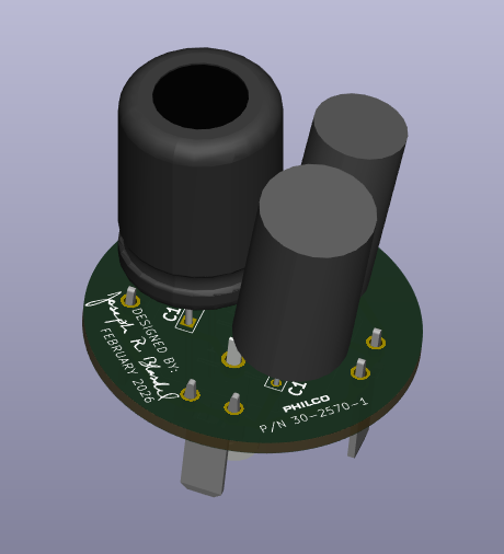
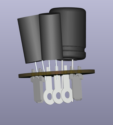
Finally, I added in the 3D models and took a look at it. Out of abundance of precaution, when I build this assembly I will sleeve the exposed leads between the PCB and the caps with some leftover braided fiberglass sleeving I have, rated up to 7kV that I have from when I resleeved the power transformer leads on my 46-480.
I recreated the design with these reduced footprints. Even so, I've got a very small amount of real estate for three capacitors. Let me explain.
The solder lugs, twist lock lugs, and capacitors are through-hole mounted. Although the diameter of the capacitor I am replacing is 1.46", I need to fit all of my connectors within this 0.86" cutout on the chassis so that nothing with a potential different than the common negative will make contact with the chassis when the PCB is mounted. This is the same constraint I had when designing the twist-lock capacitor for my 46-480 last year, but it's an even taller order in this case with three capacitors. Basically, everything except for the twist-lock connectors and possibly any other common neutral connections needs to fit within that cutout. In addition, I need to maintain minimum clearance between any components and the outline of this cutout on the chassis.
With this in mind, I reduced the two schematics into one.
I then annotated the schematic, edited the footprints to reduce their size, and then paired the new footprints to their respective schematic symbols. Finally, I created the layout. In a pink or peach color (used to represent the bottom silkscreen layer), you'll see that I added the outline of the cutout on the chassis so that I could use it for measuring clearances.
I found that I had enough space to beef up the traces to a full millimeter. I also have enough space to establish minimum creepage and clearance distances of greater than or equal to 3mm (as measured from the edges of any two adjaent surfaces or solder pads; the centerlines are spaced even further), which satisfies the IEC 60664-1 calculations (reinserting because I was actually able to satisfy even more aggressive transient overvoltage assumptions). And, again, the capacitors wil operate normally at 250V but I am designing to an operating voltage of 450V to match the value of the component I am replacing.
Finally, I added in the 3D models and took a look at it. Out of abundance of precaution, when I build this assembly I will sleeve the exposed leads between the PCB and the caps with some leftover braided fiberglass sleeving I have, rated up to 7kV that I have from when I resleeved the power transformer leads on my 46-480.
Joseph
Philco 39-750 EZ
Philco 46-480
Philco 47-1230
Philco 48-482
Philco 49-906


