



02-21-2026, 09:46 AM
Hi Jeff,
OK, by touching the grid of the 75, you received no hum. This is bad but is good. At this porint, you work "backwards" starting at the speaker, power supply, etc.
The next instructions that I give may be very basic. Please forgive me if your skills are more advanced than my instructions. In all things, please exercise caution to prevent burns and dangerous electrical shock. All numbers referred to are from the schematic. Use either the schematic on the Phorum or the one from Nostalgia Air. Note that generally, the term "cap" is shorthand for capacitor unless referring to the "grid cap" on the top of some of the tubes. "Pinouts" for the rectifier and output tube are attached. The view is from the underside of the chassis. For the 41 tube, Pins 1 and 6 are larger in diameter than the other pins.
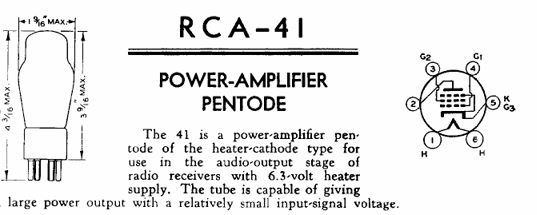
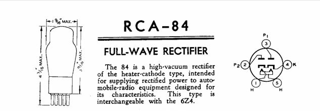
The following issues will cause no audio. Ensure that the set is unplugged. Verify resistance readings to determine:
Perform the following tests very carefully as you are exposed to dangerous or fatal voltages. Do not proceed if not comfortable or familiar with safely making voltage measurements on live line powered equipment:
There may be other issues. Please DO keep us posted; we are very happy to help you to successful completion of this project!!
OK, gang, gotta go and prepare gfor the upcoming blizzard!!
OK, by touching the grid of the 75, you received no hum. This is bad but is good. At this porint, you work "backwards" starting at the speaker, power supply, etc.
The next instructions that I give may be very basic. Please forgive me if your skills are more advanced than my instructions. In all things, please exercise caution to prevent burns and dangerous electrical shock. All numbers referred to are from the schematic. Use either the schematic on the Phorum or the one from Nostalgia Air. Note that generally, the term "cap" is shorthand for capacitor unless referring to the "grid cap" on the top of some of the tubes. "Pinouts" for the rectifier and output tube are attached. The view is from the underside of the chassis. For the 41 tube, Pins 1 and 6 are larger in diameter than the other pins.
The following issues will cause no audio. Ensure that the set is unplugged. Verify resistance readings to determine:
- Open speaker voice coil (must be checked while speaker is disconnected from the output transformer).
- Open speaker field coil. Measure with speaker connected, between + terminals of Caps #25 and 26.
- Open output transformer primary or wiring. Measure between Pins 2 and 3 of the 41 output tube for this resistance reading.
- Open resistors #23 or #24
- Open ground path between cathode of 41 output tube (pin 5) and chassis ground.
- Perform a good physical inspection of the power and audio sections of the radio. ensure that the field coil, output transformer primary and secondary are connected. Ohm the speaker voice coil. This must be done with at least one lead of the output transformer secondary disconnected from the speaker! In addition, note on the schematic, that one end of the secondary of the output transformer is grounded to the chassis, and that the other end of the secondary connects to the cathode terminal of the output tube, completing the circuit between the output tube cathode and B- (Chassis ground). If these 2 connections are not made, there will be NO AUDIO. If someone connected the cathode of the output tube directly to chassis, this would work also but would eliminate the feedback path provided to increase fidelity.
Perform the following tests very carefully as you are exposed to dangerous or fatal voltages. Do not proceed if not comfortable or familiar with safely making voltage measurements on live line powered equipment:
- With the set powered up and speaker connected, and with the meter set for DC volts at a range of 250V or higher, measure across the 12uF electrolytic cap #26. Note that this cap does NOT connect to chassis ground. The voltage should be 215VDC. If higher, don't worry for now. If low or Zero volts then there is an issue with the rectifier or the transformer. If no voltage at cap #26, switch the meter to AC 750V and measure between each plate of the rectifier tube and the center tap of the transformer (the negative lead of #26). between each plate and the center tap, there should be somewhere about 250-350VAC or so. The voltage from plate to plate will be somewhere between 400 and 800V. Measure this very carefully, preferably by sing clips instead of holding the probes as this is a dangerous voltage. If zero volts, then the transformer or its wiring is bad.
- If the voltage across cap #26 is good, then, with the DVM set for 250VDC or 600VDC measure across cap #25, the 4uF electrolytic cap. Note that the negative lead of this cap DOES connect to chassis ground. The voltage will be somewhat lower than the voltage across cap #26, in the 140-180V range. If very low or Zero volts, check between the negative lead of cap #26 and the positive lead of cap #25. If no voltage, the speaker voice coil or wiring is at fault. If the voltage s good, then resistors 23 and 24 are suspect.
- If the voltage across cap #25 is good, measure DC voltages between Pin 2 and Pin 5 of the 41 output tube. If low or Zero volts, then Resistors #23 and 24 or wiring between pin 6 and the output transformer secondary and wiring between output transformer secondary and ground is suspect.
There may be other issues. Please DO keep us posted; we are very happy to help you to successful completion of this project!!
OK, gang, gotta go and prepare gfor the upcoming blizzard!!
"Do Justly, love Mercy and walk humbly with your God"- Micah 6:8
"Let us begin to do good"- St. Francis
Best Regards,
MrFixr55


