



04-15-2026, 12:17 PM
MrFixr55, I'm going for functional and generally authentic external look. I'm not laboring over minor cosmetic alterations, but I am trying to keep the general construction and function/circuits authentic as well. So, I'm not going to replace an entire chassis with new radios, but as far as a piece like this candohm, whether it's a single unit or an assembly of individual resistors, I'm fine with the most expedient and reliable way.
Photo of the current part:
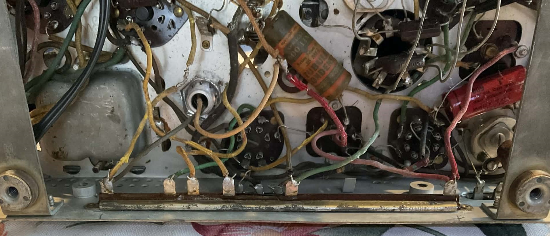
In your terminal strip scenario, you mention mounting them against the chassis - I take it you mean to solder them in place on the strip such that the bodies of the resistors can press against the chassis side without making electrical contact, like a heatsink? Is the spacing and length of the segments of importance to reproduce, or is it arbitrary and more about getting it to tie together correctly? Given that in testing the segments there were terminals in common, I presume that the resistors themselves must either have solder points in common, or a separate connection between them to connect the series. This is of course in addition to the other wires that come in from the other points in the chassis.
Separately, after following your guidance on testing R5 and R7 (I actually also checked at the base of the transformer directly as well since the R7 tested very weird at the exterior terminals), R5 tests at about 80.2K and R7 tests at 230K, so it sounds like R5 or something connected to it may be problematic. Any tips on extracting the transformer from the shield, or is it simply a matter of grinding off/drilling out the rivets?
Best wishes,
Roy
Photo of the current part:
In your terminal strip scenario, you mention mounting them against the chassis - I take it you mean to solder them in place on the strip such that the bodies of the resistors can press against the chassis side without making electrical contact, like a heatsink? Is the spacing and length of the segments of importance to reproduce, or is it arbitrary and more about getting it to tie together correctly? Given that in testing the segments there were terminals in common, I presume that the resistors themselves must either have solder points in common, or a separate connection between them to connect the series. This is of course in addition to the other wires that come in from the other points in the chassis.
Separately, after following your guidance on testing R5 and R7 (I actually also checked at the base of the transformer directly as well since the R7 tested very weird at the exterior terminals), R5 tests at about 80.2K and R7 tests at 230K, so it sounds like R5 or something connected to it may be problematic. Any tips on extracting the transformer from the shield, or is it simply a matter of grinding off/drilling out the rivets?
Best wishes,
Roy


