Restoring a Model 19 Code 126
Posts: 109
Threads: 18
Joined: Mar 2015
City: Ann Arbor, Michigan
I knew Kaplan was wrong and I went in to edit the post but it didn't take  .
Where is best article with instructions for rewinding the oscillator coil for a Model 19 /89? I checked tonight, and my tickler coil is definitely open. Can't seem to find THE instructions. Was it a Rider tip or something?
Thanks again.
Mark
Posts: 16,582
Threads: 574
Joined: Oct 2011
City: Jackson
State, Province, Country: NJ
The best way to me is: (I rewind coils this way):
1. Make a sketch. Measure the length of the winding along the bobbin, position relative to other windings. Note the way the wire goes to the first pin (choose one to be the first pin, does not matter), with the orientation of the coil noted (say, on the sketch pins to the left, top to the right), then start unwinding the coil, counting turns. When finishing the last turn, note the direction of winding, put it on the sketch.
Measure or estimate the wire gauge. If litz is used for the wire, use litz, not a single wire, it matters.
2. Connect your wire to the pin that you want to start winding from. Do not solder, just wrap the wire around it. Wind the section, as close to the original as posible: wire gauge if many turns and the coil is used in a resonant tank (if two-three turns, like in RF non-resonant transformers, it is not important as much as long as it fits, in resonant coils, lie RF winding or antenna coils that connect to tuning caps it is important), length of winding (same criteria as above), deinitely direction of winding and connection to pins.
Keeping the winding taut, thread the wire and wrap around the other pin.
Secure the winding with whatever used for that (I use fabric glue).
It takes 20 minutes tops.
3. Unwind the ends from the pins, clean and solder.
People who do not drink, do not smoke, do not eat red meat will one day feel really stupid lying there and dying from nothing.
Posts: 109
Threads: 18
Joined: Mar 2015
City: Ann Arbor, Michigan
Thanks for those tips!
I am waiting for magnetic wire to come in the mail, and I need to remove the coil. I will let you know how it turns out.
Mark
Posts: 109
Threads: 18
Joined: Mar 2015
City: Ann Arbor, Michigan
Hey guys I haven't worked with thin enameled wire since my Fun With Electronics Kit 50 years ago. How do you remove the enamel off the ends? Flat surface and the edge of a razor blade?
Any better technique?
Mark
Posts: 109
Threads: 18
Joined: Mar 2015
City: Ann Arbor, Michigan
(03-14-2015, 08:58 AM)markmokris Wrote: Hey guys I haven't worked with thin enameled wire since my Fun With Electronics Kit 50 years ago. How do you remove the enamel off the ends? Flat surface and the edge of a razor blade?
Any better technique?
Mark
Now that I think about I should probably use a fine sandpaper on the ends?
Mark
Posts: 16,582
Threads: 574
Joined: Oct 2011
City: Jackson
State, Province, Country: NJ
an exacto knife, held blade towards yoursel and moved away from youself or fine sandpaper, or quick run through the lighted match and then wipe with alcohol work
Sand paper is probably the easiest. Very fine one.
People who do not drink, do not smoke, do not eat red meat will one day feel really stupid lying there and dying from nothing.
Posts: 1,411
Threads: 71
Joined: Oct 2007
City: Linn Creek, MO
Mark, some magnet wire has an insulation with a low enough melting point that you can just wrap the terminal and solder it with the insulation on. However, some wire has a higher temp insulation and would have to be stripped.
Steve
M R Radios C M Tubes
Posts: 16,582
Threads: 574
Joined: Oct 2011
City: Jackson
State, Province, Country: NJ
I tried that with mine...did not work. But I did see a wire like this.
People who do not drink, do not smoke, do not eat red meat will one day feel really stupid lying there and dying from nothing.
Posts: 7,305
Threads: 270
Joined: Dec 2009
City: Roslyn Pa
A few years ago I got the magnet wire from a motor rewind service. That stuff had the toughest coating on it, I think it was polyurethane. Have to use a shape knife to clean it off. I think the lacquer covered wire that the solder will burn off. Used that tough stuff to wind up some new coils for my old National SW-3.
https://home.comcast.net/~wa9wfa/ha00004.htm
Gud Lk OM
Terry N3GTE
Posts: 109
Threads: 18
Joined: Mar 2015
City: Ann Arbor, Michigan
The good news is I tested the shadow meter with a 9 V battery and it works great! It deflects perfectly.
The bad news is that I accidently pulled the grid cap off the 75 tube. I'm need to be more careful with those.
Is there a substitute for the 75? I am having trouble finding one. Meanwhile I am going to try to repair it.
Mark K8KZ
Posts: 7,305
Threads: 270
Joined: Dec 2009
City: Roslyn Pa
Well an 85 will work but has a bit more gain. Did the grid wire break off at the glass? If not just solder back on.
Terry
Posts: 16,582
Threads: 574
Joined: Oct 2011
City: Jackson
State, Province, Country: NJ
Take the grid cap.
While holding it with long thin needlnose pliers, Heat the solder on top well so it melts, and shake it once vigorously over your garbage can.
See if the small hole in the midde appeared.
If it did, look at the wire coming out of the tube's center, if the glass is intact around it and if it is straight.
Do not try to straighten it unless really mushed. It is stiff and when you place the cap back it should protrude through that hole just a little. If it does appear in the hole but does not go through, heat the cap a little so it does let the wire through.
Then using rosin core solder flood the top of the cap, making sure th vwire wets well.
People who do not drink, do not smoke, do not eat red meat will one day feel really stupid lying there and dying from nothing.
Posts: 109
Threads: 18
Joined: Mar 2015
City: Ann Arbor, Michigan
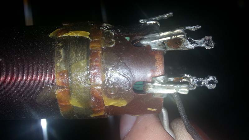
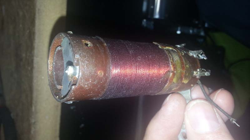
Onto rewinding the tickler coil. It seems to be the only coil that is open in the entire radio. I have removed the oscillator coil, and here are some pictures.


Pins 1 and 2 (moving clockwise from the bottom view) are the connections to the tickler coil. It looks like the existing wires go inside the form and out through some holes that I cannot see currently. They are there somewhere right?
The fact that the primary of this assembly is an internal and separate coil leaves little room to fish those wires through, but that is what I need to do when I rewind it, correct? I don't think I want to fool with removing the internal coil.
I am thinking of melting the debris (wax?) away from the existing tickler with a hair dryer. Sound like a good plan? Then remove the wire, count the turns, etc? None of this looks particularly easy, so any advice is most appreciated! I will bake the coil for 30 minutes at 200 degrees before I rewind.
I have 34, 36, and 38 gauge wire. Can I go with the 34 (the thickest)?
Thanks,
Mark
Posts: 7,305
Threads: 270
Joined: Dec 2009
City: Roslyn Pa
When you get the feedback winding off you'll see that under the winding is a strip of celluloid. That strip has a couple of slits in it that's what the wire is looped under to secure it. Wire ga is not very critical the 34ga is fine # of turns are.
Terry
Posts: 109
Threads: 18
Joined: Mar 2015
City: Ann Arbor, Michigan
I want to be sure about this process of baking the coil.
I am going to remove the old ticker portion, then bake the coil. In other words I will be baking it with both the original primary and secondary windings intact.
That is okay, right?
The primary and secondary are not open. I'd prefer not to rewind them. So it is okay to bake them, right?
Thanks,
Mark
Users browsing this thread: 1 Guest(s)
|
|
Recent Posts
|
|
Philco Model 38-7: what caps & resistors do fail typically?
|
| Since you stated earlier, you have a console 38-7XX. They also had a 38-7T (table), and 38-7CS (chairside). A very nic...GarySP — 01:18 PM |
|
Part numbers to model cross
|
| That I wouldn't know, but sometimes the radio document itself shows one, same as the capacitor cans' etc pinouts.morzh — 12:46 PM |
|
Part numbers to model cross
|
| Thank you morzh, that is exactly what I was looking for. Now , is there some where that shows pinouts for Philco power ...Jim Dutridge — 11:37 AM |
|
Restoration of the Canadian General Electric A-87
|
| Thanks for your help Michael. In fact, this video is only an intermediate result. Later I had to apply another tinting l...RadioSvit — 09:01 AM |
|
Restoration of the Canadian General Electric A-87
|
| Great job on the cabinet.
PS. In the US notation, "kenotron" refers to specific type of tubes; we call re...morzh — 08:24 AM |
|
Part numbers to model cross
|
|
This document has at least some tables of models and parts used.
Example: Choke 32-7572, used in 604 radio.
Search f...morzh — 08:19 AM |
|
Restoration of the Canadian General Electric A-87
|
| I also checked all the radio tubes on my Hickok 530 tube tester. The 5Z3 kenotron turned out to be faulty, all the other...RadioSvit — 08:02 AM |
|
Restoration of the Canadian General Electric A-87
|
|
Well... While the varnish is drying up, I started repairing the chassis...
Of course I started by replacing the pa...RadioSvit — 07:12 AM |
|
Philco Model 38-7: what caps & resistors do fail typically?
|
| Hello Martin,
Welcome aboard our little community what great Model 38-7
Sincerely Richardradiorich — 12:30 AM |
|
Philco Model 38-7: what caps & resistors do fail typically?
|
| Welcome to the Phorum Martin.
I count about 9 paper caps, the 3 electrolytic caps and 2-Y2 safety caps to replace th...RodB — 09:44 PM |
|
Who's Online
|
There are currently 1410 online users. [Complete List]
» 1 Member(s) | 1409 Guest(s)
|
|
|

|
 
|
 .
.


![[-] [-]](https://philcoradio.com/phorum/images/bootbb/collapse.png)


