Scott 16 - Restoration Begun
Posts: 1,199
Threads: 49
Joined: Oct 2017
City: Allendale, MI
Thanks, Mike, for that info. There may be a few that I'll have to do that with. but this evening I got the first row of tube sockets riveted in without a lot of difficulty. The next row is a bit more difficult as the rivets are closer and the tube shield bases get in the way. Need to make some custom bucking bars to set the rivets. So far, only very minor, invisible damage.
Posts: 2,118
Threads: 112
Joined: Jun 2010
City: Medford OR (OR what?)
(06-22-2018, 10:02 PM)mikethedruid Wrote: I know it isn't original, but I just replace the rivets with little pan head screws, internal lock washers, and little hex nuts. Less chance of damaging anything putting them in, and you don't need special tools. Of course, someone really picky may notice it, but that's THEIR problem for being too anal about such things. It's how we did it back in the day, and it's good enough for me now.
That is what most people do - that is what I have done, especially if it is only one, say, a socket replacement on an average radio. BUT after you pay $400 or more to have a chassis re-chromed it is hard to settle for non-stock hardware. So keep that hammer warmed up - -
"I just might turn into smoke, but I feel fine"
http://www.russoldradios.com/
Posts: 1,199
Threads: 49
Joined: Oct 2017
City: Allendale, MI
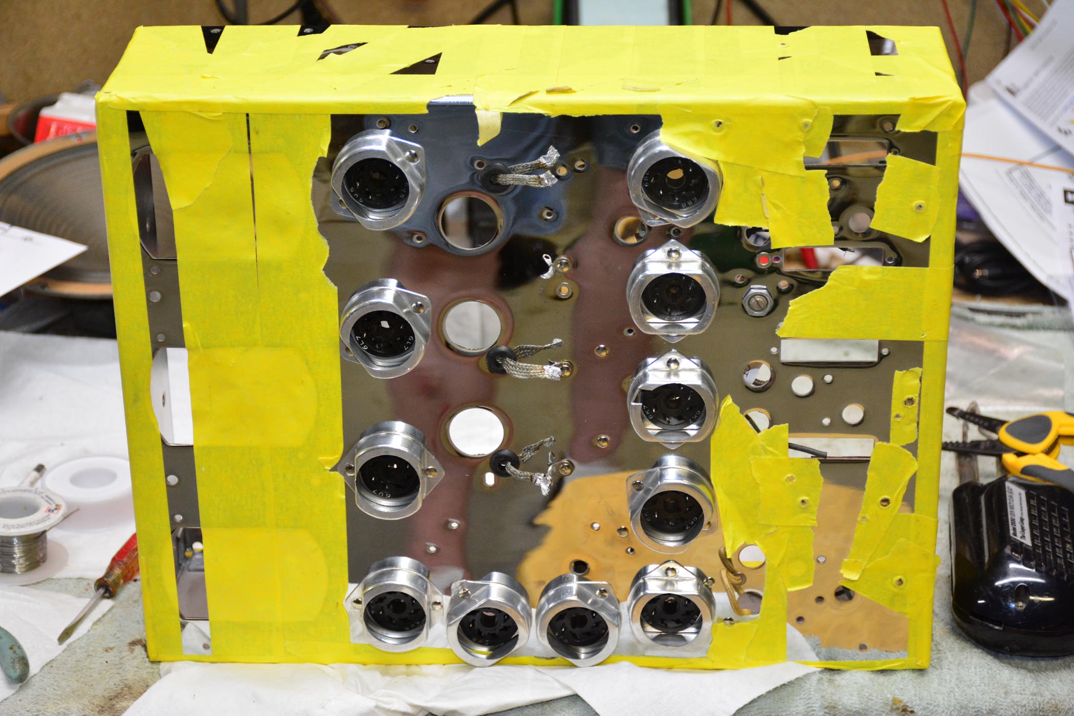
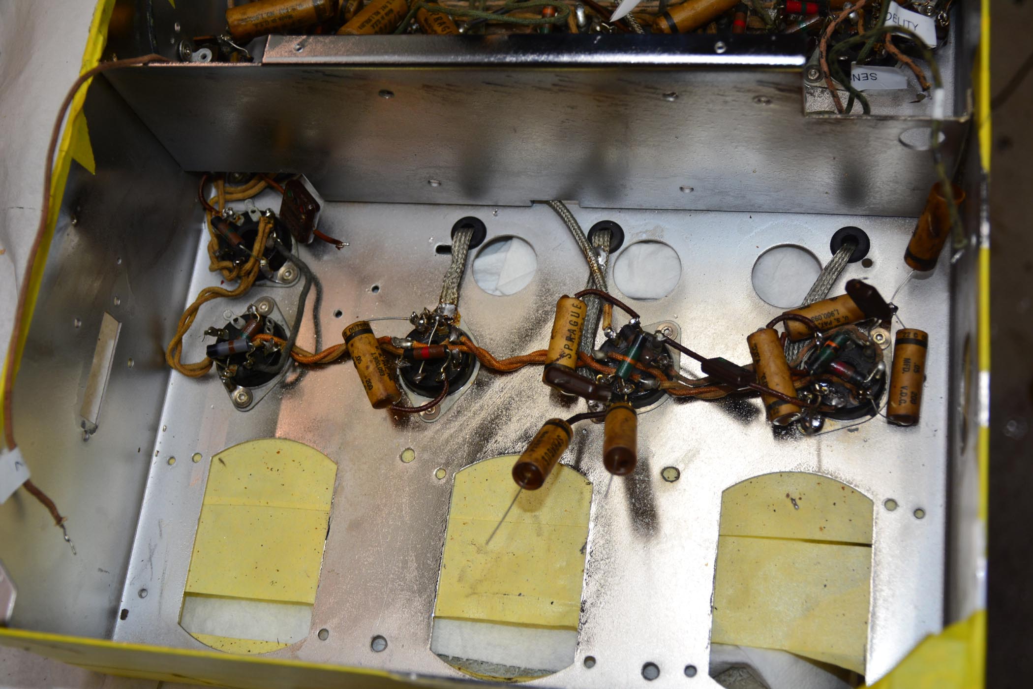
Here's where I'm at so far. Tube sockets and several terminal strips have been riveted in place. A few tubular caps have been re-stuffed with a lot more to go.
Chassis with some protective masking tape:
These caps re-stuffed and resistors checked:
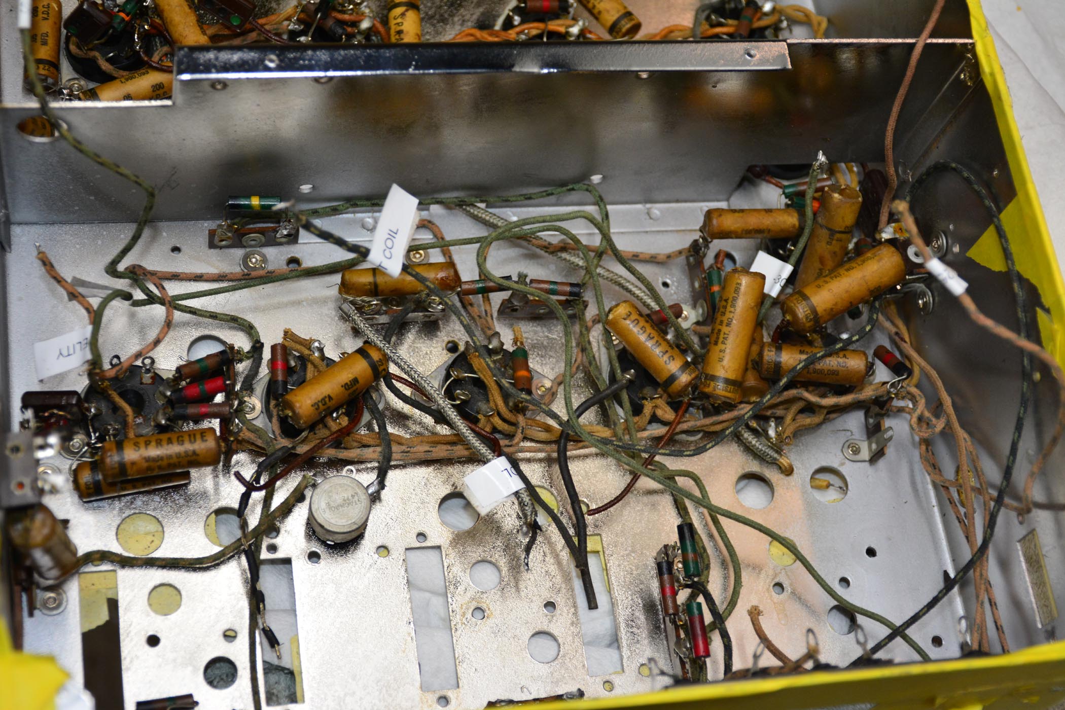
These caps are next:
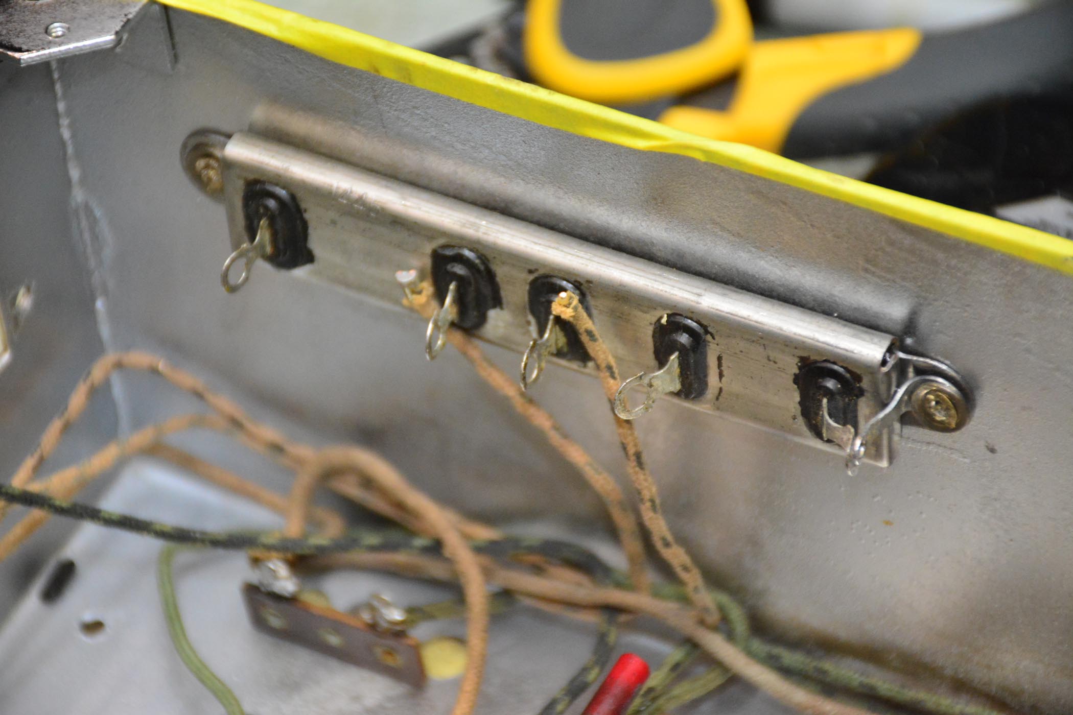
The candohm resistor was opened up and the entire insides were encapsulated in some sort of resin. I took a dremel tool and cut through the resin and the windings to open up all of the sections. I'll use the terminals as a terminal strip to hide the black Dale resistors as best I can.
Posts: 1,199
Threads: 49
Joined: Oct 2017
City: Allendale, MI
Posts: 1,475
Threads: 69
Joined: Nov 2012
City: Kansas city, MO.
Great looking work on the Scott 16.   I was wondering how you were coming along with the restoration.
Posts: 1,199
Threads: 49
Joined: Oct 2017
City: Allendale, MI
Just recently got back to it. Was out of commission for a couple of months.
Posts: 1,199
Threads: 49
Joined: Oct 2017
City: Allendale, MI
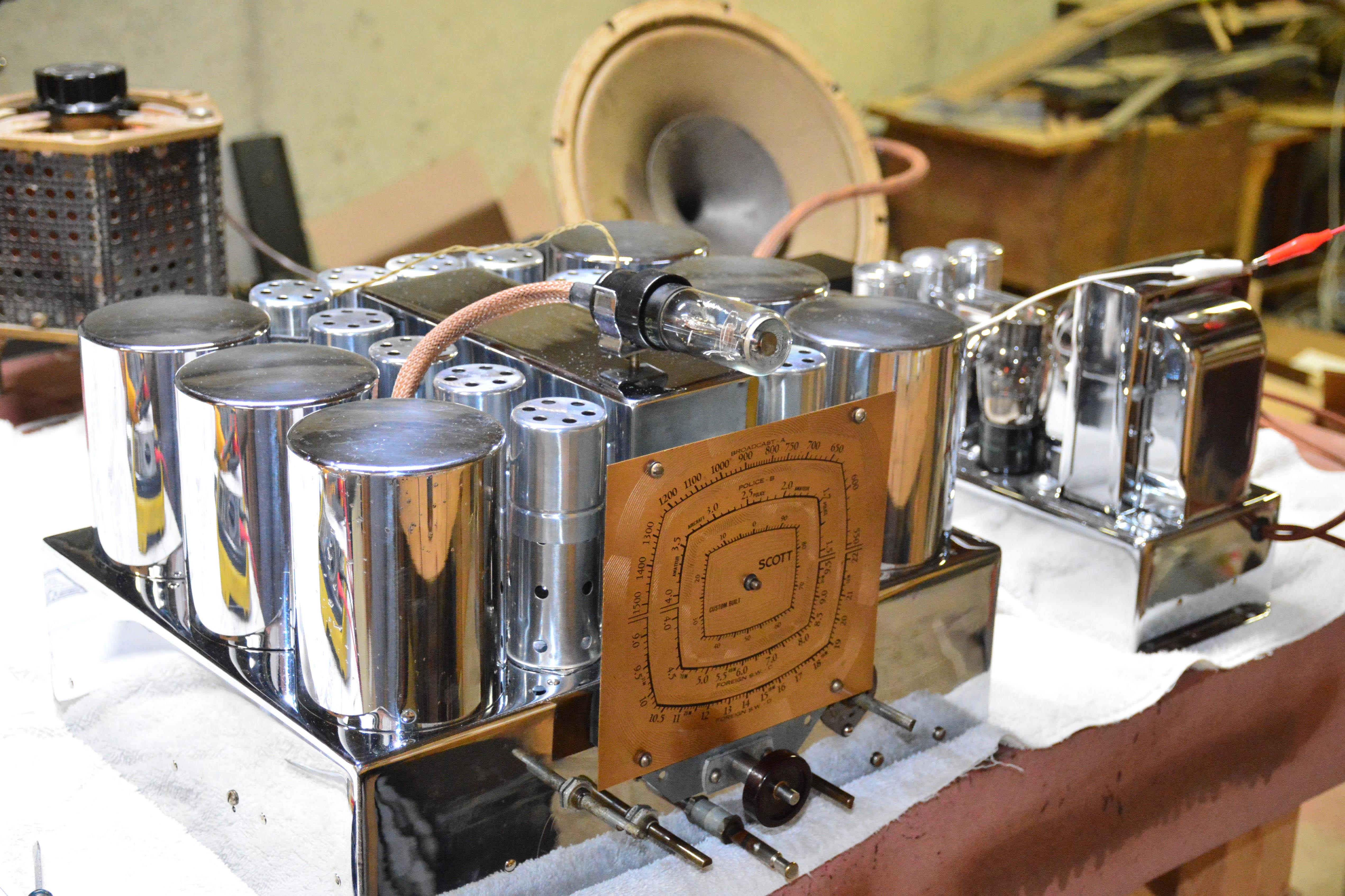
I love it when things work first shot out of the box! Powered it up slowly this evening. Started to get stations all across the dial at about 75 volts. Works great at full voltage with all bands pulling in stations. Now for a complete alignment and a few other minor things such as dial needle and dial lights. Then the cabinet. Nice to finally be this far.
Posts: 1,475
Threads: 69
Joined: Nov 2012
City: Kansas city, MO.
First power up. That's always the exciting part to me after hours of working on a radio.
Will it work or not. 
Posts: 1,199
Threads: 49
Joined: Oct 2017
City: Allendale, MI
The proper IF frequency for this radio is 465kc. I suspect it had been set at 455 at some point in time as I had to turn the trim caps a considerable amount to peak it at 465. Then, my dial was off by about 10kc. I've realigned everything and all bands now track very well. Things seem to work quite well. It sounds pretty good even with the speaker out in the nude. However, it's still AM with all of the associated noise. I like FM! Now I need to attend to the cabinet.
Posts: 1,199
Threads: 49
Joined: Oct 2017
City: Allendale, MI
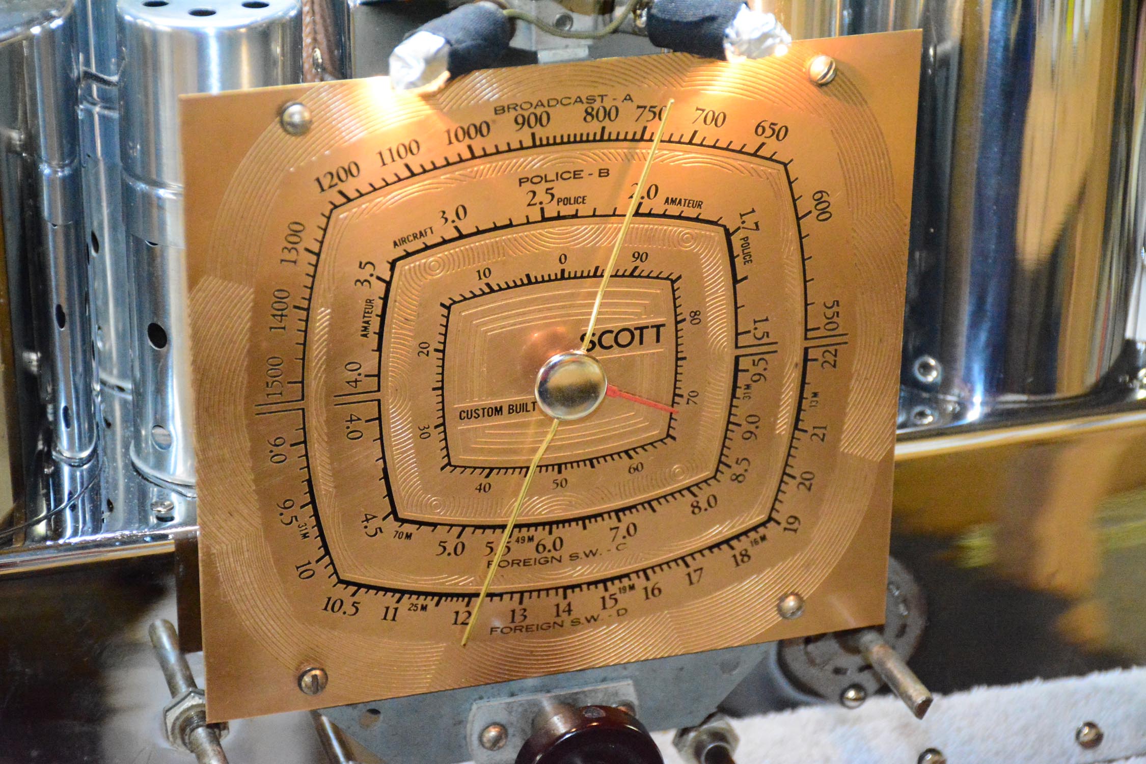
Until such time as I can find an original needle for the dial, this will have to do. It works and doesn't look too bad.
Posts: 1,199
Threads: 49
Joined: Oct 2017
City: Allendale, MI
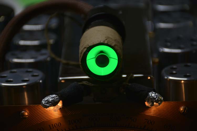
I needed a new 6E5 for this radio and found some cheap Toyo brand on Ebay. I decided to try them. It's nice and bright but the gain in the triode section must be pretty high. Most stations fully close the eye even though the control for eye sensitivity is turned all the way down! I should be able to modify that. Nice to have such a bright indicator.
Posts: 102
Threads: 14
Joined: Jul 2017
City: Bakersfield, CA
I'd love to see the rest of what you've done. I have a 16 and am very interested in what a complete job you've done. Is there more somewhere?
Scott
Posts: 1,199
Threads: 49
Joined: Oct 2017
City: Allendale, MI
This thread is it, Scott. But it is 4 pages long! Starts at the beginning with a complete strip down and re-chroming, and ends up here. If you have questions, please feel free to ask! You can post here or PM me. I'd love to help!
The radio chassis still sits on one of my benches. The Acousticraft cabinet still needs to be refinished. It sound pretty good even though the speaker is not in a cabinet. All capacitors were re-stuffed and all of the resistors were replaced (but not molded to look original.) Both of the chassis were re-chromed but the IF shield cans were not - maybe someday if I find a reliable shop. I have a couple of EH Scott Philharmonic's now that I'm more interested in! The one I have running is awesome!
(This post was last modified: 04-26-2020, 12:35 AM by rfeenstra.)
Users browsing this thread: 1 Guest(s)
|
|
Recent Posts
|
|
Philco 42-345 Restoration/Repair
|
| Hi OSanders,
Look carefully at the band switch. Turn it slowly and "wiggle" it around the desired band. ...MrFixr55 — 12:33 AM |
|
5U4 vs 5Z4 tubes
|
| I think that RCA and GE introduced metal tubes in the USA in 1936. I don't know if they were being made by RCA, GE or b...MrFixr55 — 11:20 PM |
|
Philco 42-345 Restoration/Repair
|
| Vlad95,
Thank you for the stringing guides and wow there are so manyosanders0311 — 06:01 PM |
|
5U4 vs 5Z4 tubes
|
| A pre war Hallicrafters, and an early one too, very nice! 1936 is pretty early for metal tubes too, which would explain ...Arran — 05:58 PM |
|
Philco 42-345 Restoration/Repair
|
| Thanks Rod,
"When you hear the background hiss and no station it usually indicates that the oscillator quit" ...osanders0311 — 05:52 PM |
|
Philco 42-345 Restoration/Repair
|
| RodB
:beerchug:Vlad95 — 10:22 AM |
|
Philco 42-345 Restoration/Repair
|
| Vlad, you nailed it. Swiss and German roots.RodB — 09:54 AM |
|
5U4 vs 5Z4 tubes
|
| Well this is a Hallicrafters SX/9 circa 1936.
No real issues so far although I dodged a real bullet with a cap that was...bridkarl — 07:59 AM |
|
5U4 vs 5Z4 tubes
|
| The pinout is the same but the 5U4 has a 3 amp filament, verses 2 amps or less on the 5Z4. I think that the pinout of a ...Arran — 12:04 AM |
|
Philco 42-345 Restoration/Repair
|
| By the way.
osanders0311
Take a look here: Dial cord stringing Guides
May be here you can fount correct string settin...Vlad95 — 11:15 PM |
|
Who's Online
|
| There are currently no members online. |

|
 
|


![[-] [-]](https://philcoradio.com/phorum/images/bootbb/collapse.png)


