Posts: 1,199
Threads: 49
Joined: Oct 2017
City: Allendale, MI
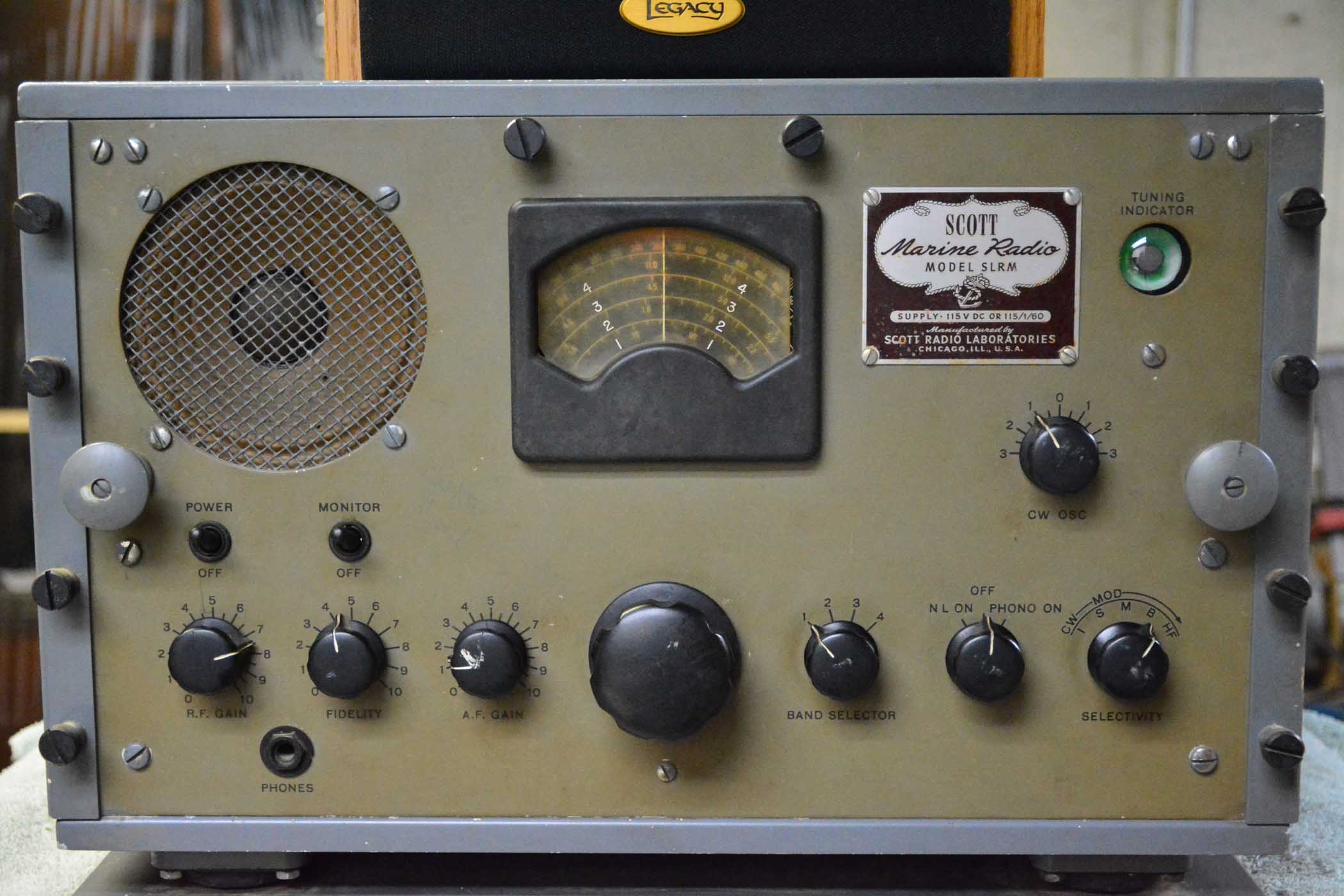
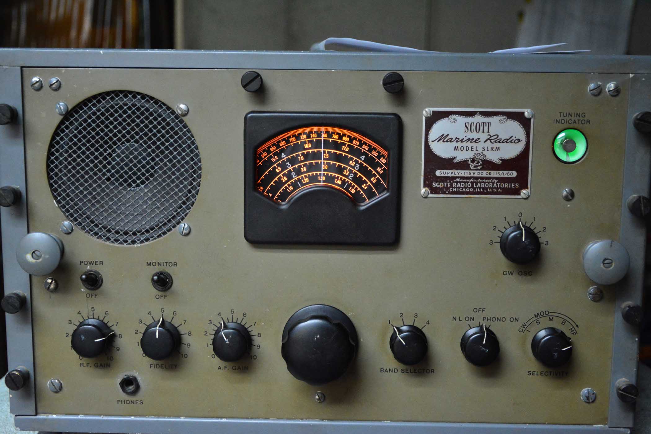
Bought this from Ron. Thanks Ron. Studied the parts list and discovered that all the coupling caps are mica and the bypass caps are bathtub type - oil soaked. Disconnected and checked a couple and they checked fine, same with the mica's. Decided to power it up slowly, monitoring the B+. B+ was fine and ripple was very low. The radio came to life without hum! Checked all voltages (the Scott manual is very complete) and all are reasonable but some are off a bit. Some resistors have drifted high, but not too far out of spec. The biggest problem I have is the brightness of the pilot lamp. This is an AC-DC set so no PT. The pilot is in the return line to the negative supply and it appears to be the correct lamp. Without the pilot light, the radio is dead. I may play with some form of LED to supplement the pilot lamp. I'll probably re-stuff the electrolytic cans just to be safe and take my chances on the rest, at least until problems develop. Sensitivity and selectivity (variable) is excellent. I found a couple of CW transmissions and tested the BFO - it works. With an external speaker, it really sounds pretty good. The output is designed to feed multiple speakers (like a 70 volt system) or a low impedance balanced line to drive amplified speakers throughout a ship. It uses 25L6's for the output.
The construction of this thing is amazing. No expense was spared. Every component is identified by number on the chassis for easy service by barely qualified techs in the WWII Navy, and for people like me. Great quality is as simple as tax money can make it!
I feel much safer using this radio as my enemies won't be able to zero in on my local oscillator transmission when I'm listening to the radio. After all, that's part of the reason this radio was designed.
Thank you Ron. Love it!
Posts: 1,199
Threads: 49
Joined: Oct 2017
City: Allendale, MI
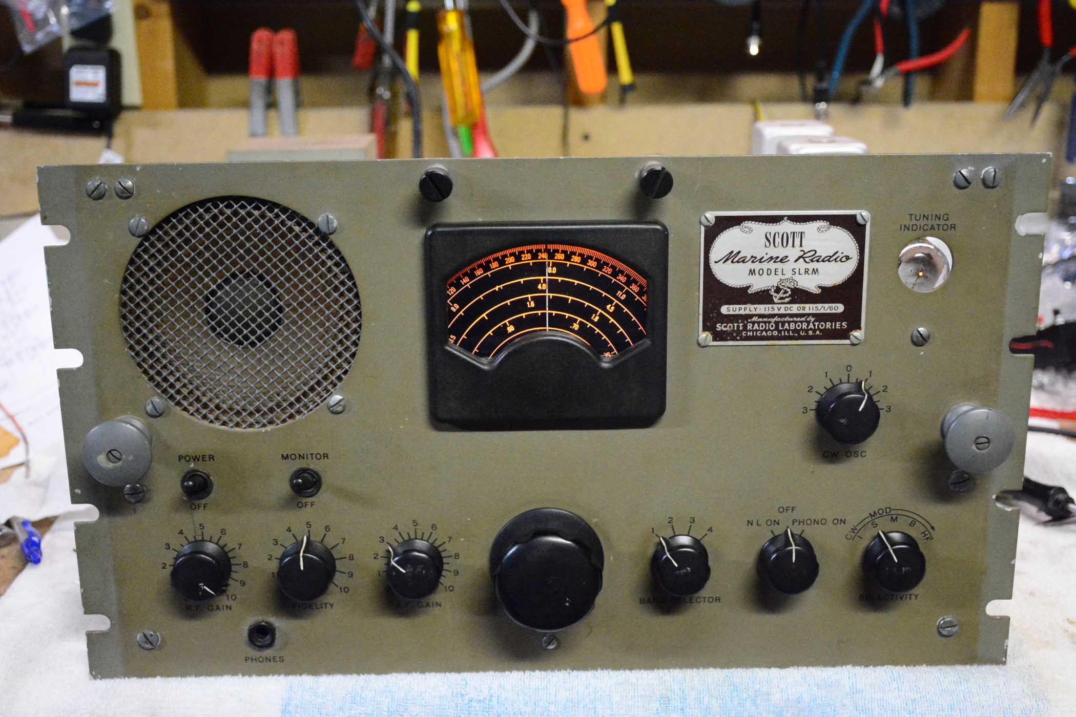
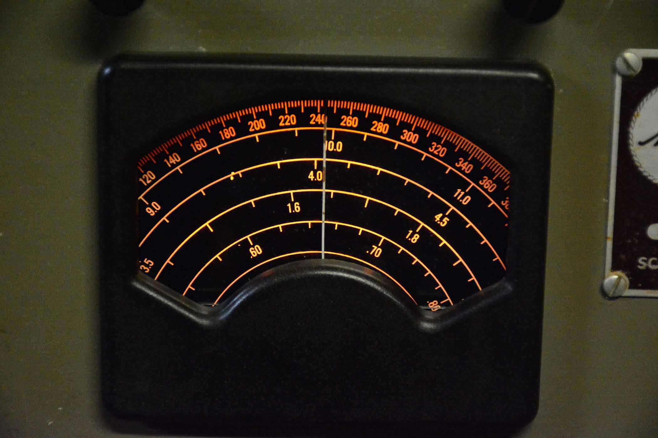
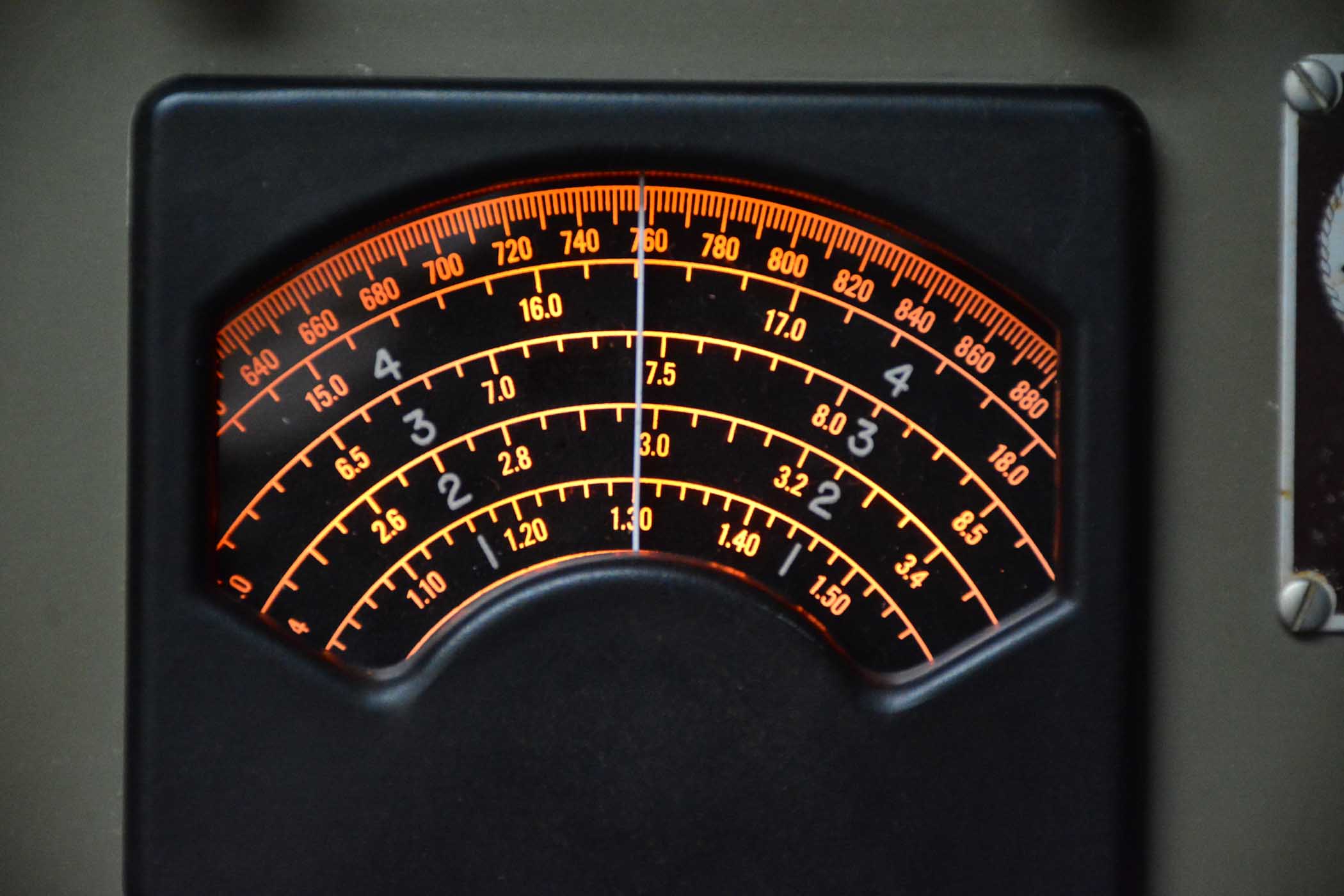
I replaced the yellowed and shrunken dial glass with a new piece of clear plastic. I need to figure out how to engrave the band numbers in the plastic to make it like the original. The original was cracked, loose, and very yellowed since it had shrunk and broke out of the pins that held it in place. LED's powered from the negative supply now back lights the dial making it easier for me to read. Compare it to the previous picture. My "magic eye" tube, a military 1629, died so I had to use a 12 volt tube with the rest of the pins cut off to provide continuity in the series filament line to get the other tubes to light. I have a NOS on order. I've also ordered new electrolytic's, all 60 mfd at 250 volts, to stuff the cans even though there is no hum at this point. I'll replace those and a couple of "dry electrolytic's that are bathtub style. Voltage measurements show no leakage in the rest of the paper bathtub caps, so I'll wait a while before replacing those.
This radio performs very nicely. Once I replace the filter caps, I'll re-align to peak it's performance and align the dial a bit better. It's not that far off, though. I'll also get the 4" pm speaker re-coned since it occasionally buzzes. The cone is warped a bit. Enjoyable project!
Posts: 3,156
Threads: 56
Joined: Apr 2011
City: Lexington, KY
That's a very nice radio. I saw it in Ron's pictures and even glanced at it when we visited but didn't think much about it. Now seeing it pictured in this thread i really appreciate it and I'm very glad it found a good home.
John KK4ZLF
Lexington, KY
"illegitimis non carborundum"
Posts: 13,776
Threads: 580
Joined: Sep 2005
City: Ferdinand
State, Province, Country: Indiana
+1. You're doing a fine job with it, Rob!  It is great to see it coming back to life.
The new dial plastic really makes that dial look good, even if it doesn't have the "4-3-2-1" numbering.
--
Ron Ramirez
Ferdinand IN
Posts: 1,199
Threads: 49
Joined: Oct 2017
City: Allendale, MI
Yes, the original plastic made the dial difficult to read. Plus, the normal pilot is so dim and shines only on the top of the dial. The LED's distributed across the back side really brightens it up. I like it even if it is not original. Now if I could find someone who could engrave the numbers in the plastic....
Posts: 1,199
Threads: 49
Joined: Oct 2017
City: Allendale, MI
Well crap! I re-stuffed the 4 electrolytic cans with new Nichicons and now I have hum that I didn't have before. All of the mil spec electrolytic cans were still very moist inside and were obviously doing a good job. After re-checking the wiring a dozen times and comparing it to the pics I took before disassembly, I know it is wired as before. Disconnecting individual sections and substituting with external caps does nothing to improve the situation. Increasing capacitance does nothing. Ripple voltage after the filter choke is a mere .027 volts, about the same as before the re-stuff. Negative supply dropped from just over -7 volts to -6.8 volts. Scratching my brain a bit here!! Radio still works great, just don't like the background hum.
Posts: 2,118
Threads: 112
Joined: Jun 2010
City: Medford OR (OR what?)
Going from my aging memory, I seem to recall that one of the filter cans in my SLR-H was an oil filled unit rated at 500V or more. If a 450V electrolytic is used here it will leak until it pops as will a tacked-on replacement. I do not know what the oil is in these caps - be careful.
https://www.russoldradios.com/blog/40-old-radios
At the bottom of the post.
Russ
"I just might turn into smoke, but I feel fine"
http://www.russoldradios.com/
Posts: 1,199
Threads: 49
Joined: Oct 2017
City: Allendale, MI
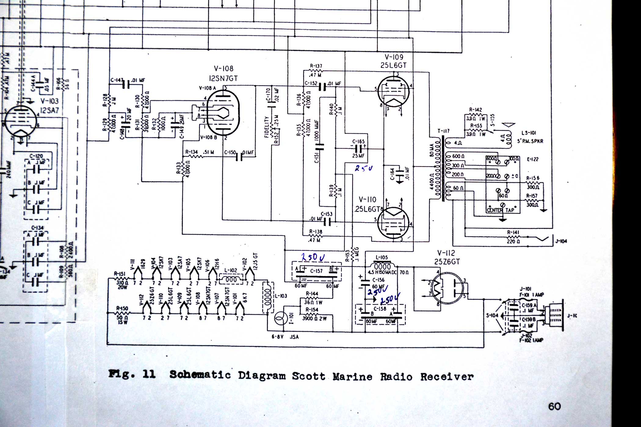
That looks like a bit more extensive of a radio than mine. maximum DC voltage in this thing is about 120 volts so the electrolytic cans were rated at 200 volts. Most of the sections were 60mfd. I used 60 mfd Nichicon's rated at 250 volts. I purchased the caps with the longest life and highest ripple voltage capability. This radio uses a ground buss that is separate from the chassis ground. Chassis ground runs abut 7 to 10 volts negative compared to the ground buss (I can vary that voltage by changing the pilot lamp) and this provides the grid bias for the 25L6's. The ground buss is the negative side of C-157. The negative line is the neutral of the AC in. Notice C-158. The A partition is the first filter cap for the half wave rectifier. The B portion filters the chassis ground to negative line. One would think that chassis ground would be riding some small positive voltage above the negative line. It does not. Chassis ground is about .05 volts negative from the negative line, putting C-158B slightly in reverse polarity mode Very slightly. When I turn the radio off, that voltage jumps to about 20 volts reverse polarity and then slowly dissipates. I get a little concerned about what this reverse polarity will do to the cap over time. Interestingly, there was a 47k resistor across this cap that is not on the schematic, nor is it called out on the chassis as every other component is. I wonder if that resistor was added reduce the effect of the reverse polarity.
Any ideas from some of you EE people who can analyze the design better than I can?
Posts: 1,199
Threads: 49
Joined: Oct 2017
City: Allendale, MI
Found the cause of the hum. It's a ground loop through the house wiring. The reason I didn't hear it before is that it was plugged into a different circuit. The hum is gone if I plug it into that same outlet. Neutral to ground on the "hum" outlet is about .5 volt AC, enough to cause the hum. Looking at the schematic, the chassis is tied to the ground lug, while the neutral is the negative line. The two are tied together at the electrical box generating a nice ground loop. Part of what tipped me off is the fact that I noticed the hum increased ever so slightly when I turned on my Scott 16A, which was on the same circuit. Finished an alignment so all of the bands are almost perfectly on. It tracts very well except it is off slightly at the extreme ends of the dial. The speaker is in getting re-coned as it was warped and distorting. I changed a couple of dry electrolytic's that are in bathtubs and the line caps with safety caps. They were also in a bathtub. I'm going to leave everything else for a year or so, then revisit the voltages and see if the resistors drift any farther out of tolerance. A few are a bit more than 20% high. I'm hoping all of the coupling caps, which are high value mica's, will hold up. The bypass caps are all oil bath type paper and seem to be ok. We'll see!
(This post was last modified: 04-11-2019, 06:46 PM by rfeenstra.)
Posts: 1,199
Threads: 49
Joined: Oct 2017
City: Allendale, MI
A fellow collector in the UK made a new dial plastic with the band numbers engraved as the original. Nice! Thanks Mike in the UK!
Posts: 3,156
Threads: 56
Joined: Apr 2011
City: Lexington, KY
Nice, very nice!
John KK4ZLF
Lexington, KY
"illegitimis non carborundum"
Posts: 13,776
Threads: 580
Joined: Sep 2005
City: Ferdinand
State, Province, Country: Indiana
Beautiful! Outstanding job by Mike H. 
--
Ron Ramirez
Ferdinand IN
Users browsing this thread: 1 Guest(s)
|
|
Recent Posts
|
|
Philco 42-345 Restoration/Repair
|
| Ok MrFixr55,
I have tried the DeoxIT D5 on the band switch and even though it has relieved the tension I felt when turn...osanders0311 — 11:11 AM |
|
Part numbers to model cross
|
| Is there a reference somewhere where you can punch in Philco part numbers and see what models those parts were used in?Jim Dutridge — 10:17 AM |
|
Philco 42-345 Restoration/Repair
|
| Hi OSanders,
Look carefully at the band switch. Turn it slowly and "wiggle" it around the desired band. ...MrFixr55 — 12:33 AM |
|
5U4 vs 5Z4 tubes
|
| I think that RCA and GE introduced metal tubes in the USA in 1936. I don't know if they were being made by RCA, GE or b...MrFixr55 — 11:20 PM |
|
Philco 42-345 Restoration/Repair
|
| Vlad95,
Thank you for the stringing guides and wow there are so manyosanders0311 — 06:01 PM |
|
5U4 vs 5Z4 tubes
|
| A pre war Hallicrafters, and an early one too, very nice! 1936 is pretty early for metal tubes too, which would explain ...Arran — 05:58 PM |
|
Philco 42-345 Restoration/Repair
|
| Thanks Rod,
"When you hear the background hiss and no station it usually indicates that the oscillator quit" ...osanders0311 — 05:52 PM |
|
Philco 42-345 Restoration/Repair
|
| RodB
:beerchug:Vlad95 — 10:22 AM |
|
Philco 42-345 Restoration/Repair
|
| Vlad, you nailed it. Swiss and German roots.RodB — 09:54 AM |
|
5U4 vs 5Z4 tubes
|
| Well this is a Hallicrafters SX/9 circa 1936.
No real issues so far although I dodged a real bullet with a cap that was...bridkarl — 07:59 AM |
|
Who's Online
|
There are currently 1192 online users. [Complete List]
» 3 Member(s) | 1189 Guest(s)
|
|
|

|
 
|


![[-] [-]](https://philcoradio.com/phorum/images/bootbb/collapse.png)


