Restoring a Philco 71 Code 121-No sound
Posts: 23
Threads: 3
Joined: Feb 2021
City: Durham
State, Province, Country: NC
This radio has an inoperative On-Off switch. I jumpered a bypass on the switch to allow the radio to power on. Voltages are about 10% above spec on the plates and within spec on the screen grids. Filament voltages are spot on. All tubes have been tested OK. Filaments and dial light are lit. My line voltage is 115 volts AC but when I measure the voltage on P/N 49 (the Bakelite block that encloses 2 x 0.015 safety capacitors [I just replaced these within the block after removing the contents], I am getting a 55.6 volt reading on the side leg that connects to the On-Off switch. Also, there is no sound at all (even static or hum) coming out of the speaker. Incidentally, another 71-B that I rebuilt has the same voltage on the Bakelite leg as the line voltage.
Could this be an issue with the transformer ?
Posts: 16,577
Threads: 574
Joined: Oct 2011
City: Jackson
State, Province, Country: NJ
One thing you should not be interested in is that very reading on the C49.
What you reading is, well, the 115VAC divided by two by your capacitors. If you tried to read it relative to the chassis.
Proceed with the essential stuff; this is just unimportant.
Your xfmr is fine and your readings that are 10% up are fine.
People who do not drink, do not smoke, do not eat red meat will one day feel really stupid lying there and dying from nothing.
Posts: 23
Threads: 3
Joined: Feb 2021
City: Durham
State, Province, Country: NC
I started looking at the oscillator coil (P/N 13) and according to the ohms readings found what I suspect is an open coil.
Readings are as follows:
Between pins 2 and 5 : 9.3 ohms
Between pins 1 and 3 : 6.6 ohms
Between pins 4 and 5 : 5.2 ohms
Between pins 2 and 4 : 4.5 ohms
Between pins 3 and 5 : 0 ohms (open ?)
Note: pins are numbered clockwise 1 to 5 from the top (12 o'clock) position mounting bracket
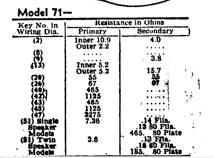
The chart for the reference ohms resistances list the following:
Primary (inner) : 5.2 ohms
Primary (outer) : 5.2 ohms
Secondary (outer) : 15.7 ohms
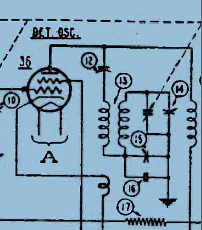
I'm thinking the open circuit is the secondary if I'm reading the schematic correctly.
Question: Which coil should I attempt to rewind and can someone tell me how to find the beginning and the end connections of such coil ?
Posts: 23
Threads: 3
Joined: Feb 2021
City: Durham
State, Province, Country: NC
Screenshot of Philco 71 Oscillator Coil (P/N 13) from Rider's
Posts: 23
Threads: 3
Joined: Feb 2021
City: Durham
State, Province, Country: NC
Posts: 23
Threads: 3
Joined: Feb 2021
City: Durham
State, Province, Country: NC
Philco Model 71 Transformer/Coil Resistance Ohms Data
Posts: 715
Threads: 9
Joined: Apr 2018
City: S. Dartmouth
State, Province, Country: MA
One can apply this to most any RF/IFoscilator coil:
If the resistance given is any more than 10% high using an analog ohmmeter then there is corrosion present and some of the turns have been etched. Often seen as tiny green spots. Such a coil may still work...
Coils that have a layer separated with what appears to be plastic, it is actually celluloid, are always suspect. In moisture/time celluloid breakdown and creates an acid. Thus etching the turns despite the enamel..
The coil will either have to be replaced or re-wound.
To re-wind, using solvent and or heat remove all the surface wax. The start/finish of the turns can be found.
I suggest creating a diagram of the coil so all notes of how it is wound are present on the diagram.. Measure the O.D. of the magnet wires and refer to a chart to determine what size magnet wire to use. Do NOT change the wire size or the number/direction of the turns.
>>> If a coil is rewound exactly as it was, it will work with very little or no alignment required. Use magnification, count the turns. Then, unwind, counting turns a second time
Clean the form, then dip in melted bees wax and let sit for a few minutes. then remove the form, it will have a wax film on it which will aid greatly in the rewind. Follow the diagram and rewind. Kapton tape can replace the rotting celluloid liner. Coat the surface of the tape or dip in wax to make the form sticky again. Wind the top layer. Dip the entire coil in bees wax and let sit, when most bubbles have gone extract from wax and let cool. The, dip very quickly to make thick film of wax, coil is now ready to back into radio.
Use only clean bees-wax not paraffin or a candle blend. Paraffin is slippery not sticky... If there are any tags of black adhesive holding the magnet wire, that, is a production wax that melts at a higher temperature. generally that black wax does not have to be replicated as one is hand winding.
The advantage of the wax and the diagram is one can take a break from the winding and the coils will not slip off and the the process not forgotten as it is on paper.
GL
Chas
Pliny the younger
“nihil novum nihil varium nihil quod non semel spectasse sufficiat”
Posts: 23
Threads: 3
Joined: Feb 2021
City: Durham
State, Province, Country: NC
Thank you for these very thorough instructions Chas. In your opinion should I rewind just the outer core top and bottom and leave the inner core intact ?
Also, which sections correspond to the primary and secondary windings ?
Posts: 16,577
Threads: 574
Joined: Oct 2011
City: Jackson
State, Province, Country: NJ
>> Between pins 3 and 5 : 0 ohms (open ?)
0 Ohms is shorted.
The lower winding seems charred?
People who do not drink, do not smoke, do not eat red meat will one day feel really stupid lying there and dying from nothing.
Posts: 23
Threads: 3
Joined: Feb 2021
City: Durham
State, Province, Country: NC
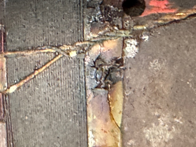
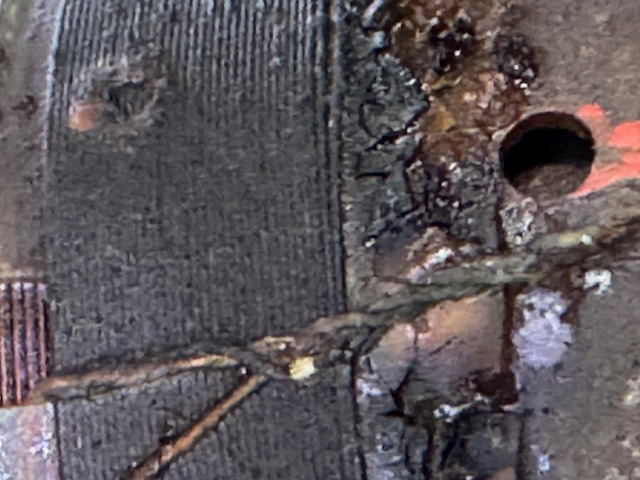
Here are some more close-ups of the Lug 5 vicinity. Appears to be a burnt out spot on the lower winding. Also, you can see it appears to have three strands of magnet wire descending to the lug. Is the lower band considered the "tickler" and the windings directly beneath that the secondary winding ? I have not been able to find a diagram to differentiate primary vs secondary, tickler, etc. , inner vs outer core.
Posts: 715
Threads: 9
Joined: Apr 2018
City: S. Dartmouth
State, Province, Country: MA
That is the “burnt” look is the Celluloid decomposing.
Once the coil/form are cleaned with solvent the condition of the coil can be examined any tiny green spots are nitric acid corrosion. The coil will have to be rewound.
Mineral spirits or alcohol.
Chas
Pliny the younger
“nihil novum nihil varium nihil quod non semel spectasse sufficiat”
Posts: 23
Threads: 3
Joined: Feb 2021
City: Durham
State, Province, Country: NC
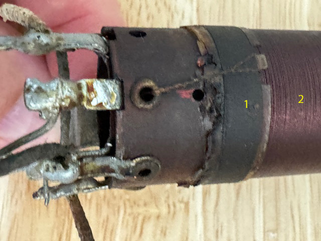
May I ask if anyone can identify the components numbered 1 and 2 in the photo. I'm trying to determine the order of removal and replacement of the coil windings.
Thank you
Posts: 16,577
Threads: 574
Joined: Oct 2011
City: Jackson
State, Province, Country: NJ
Why remove the 2?
People who do not drink, do not smoke, do not eat red meat will one day feel really stupid lying there and dying from nothing.
Posts: 23
Threads: 3
Joined: Feb 2021
City: Durham
State, Province, Country: NC
My guess is that the 3 to 5 is the secondary and it is open according to my readings but I do not actually know which of these is the secondary winding. Haven't been able to see any diagrams as to which is which. Is the small band (#1) the secondary winding ?
Posts: 16,577
Threads: 574
Joined: Oct 2011
City: Jackson
State, Province, Country: NJ
In RF interrstage transformers the small one is typically the plate load, that is the primary.
People who do not drink, do not smoke, do not eat red meat will one day feel really stupid lying there and dying from nothing.
Users browsing this thread:
|
|
Recent Posts
|
|
5U4 vs 5Z4 tubes
|
| Well this is a Hallicrafters SX/9 circa 1936.
No real issues so far although I dodged a real bullet with a cap that was...bridkarl — 07:59 AM |
|
5U4 vs 5Z4 tubes
|
| The pinout is the same but the 5U4 has a 3 amp filament, verses 2 amps or less on the 5Z4. I think that the pinout of a ...Arran — 12:04 AM |
|
Philco 42-345 Restoration/Repair
|
| By the way.
osanders0311
Take a look here: Dial cord stringing Guides
May be here you can fount correct string settin...Vlad95 — 11:15 PM |
|
5U4 vs 5Z4 tubes
|
| 5U4 and 5Z4 almost identical. I think nothing happened if you left 5U4 instedad 5Z4 long time.
Just heater current 5U4 ...Vlad95 — 11:02 PM |
|
Philco 42-345 Restoration/Repair
|
| Hello Vlad95 ,
Very Funny !
Sincerely Richardradiorich — 11:01 PM |
|
Philco 42-345 Restoration/Repair
|
| RodB
You are European yourself :evil:
I'm Canadian for the last 30 years :snowman:
But not Yankee :lol: Vlad95 — 10:49 PM |
|
Philco 42-345 Restoration/Repair
|
| The band switch selects different oscillator coils for the band selected. I would look for a bad connection in the switc...RodB — 10:31 PM |
|
Philco 42-345 Restoration/Repair
|
| Hang in there...PaulPaul Philco322 — 09:30 PM |
|
Philco 42-345 Restoration/Repair
|
| The thrill is gone again, thought I was close to being done with it. Well Friday it was receiving broadcast, Saturday mo...osanders0311 — 07:47 PM |
|
Help with Supreme 599
|
| Iam getting closer to fixing it. I bumped
Up the tranny voltage to get 5v on the 80 tube. I gan get the needle to move ...daveone23 — 03:41 PM |
|
Who's Online
|
| There are currently no members online. |

|
 
|


![[-] [-]](https://philcoradio.com/phorum/images/bootbb/collapse.png)


