Restoration of the Canadian General Electric A-87
Posts: 746
Threads: 24
Joined: Nov 2014
City: Svalyava. Transkarpatia
State, Province, Country: Ukraine
Ok.... In the fourth year of the war, I still decided to return to an active hobby. For more than three years, I did not restore radio cabinets, but only occasionally did small repairs. As I already wrote here, a well-known friend of mine from my small town before the war received a contract to work in Canada near Ottawa and this winter accidentally came across a sale of a rather large collection, remembered my hobby and offered a deal that I could not resist.  Namely - for a complete restoration and restoration of about 10 radios, I will be able to choose several of the best as payment for the services provided. Considering that I am already retired and have much more free time, I simply could not help but agree. Especially considering that I will have the opportunity to better familiarize myself with and study many unique radios from Canada and the USA.
So, the first radios started arriving in early March. And the first was the Canadian General Electric A-87. Since it was shipped by the economical "sea delivery" option by the Meest Express company, the delivery time was two months. If you do not take into account the small damage to a piece of veneer, then we can assume that the journey of this radio console to Ukraine was successful. 


Old tube radios and gramophones museum TV channel
https://www.youtube.com/user/RadioSvit
Sincerely Peter
З повагою Петро
(This post was last modified: 06-15-2025, 10:45 AM by RadioSvit.)
Posts: 746
Threads: 24
Joined: Nov 2014
City: Svalyava. Transkarpatia
State, Province, Country: Ukraine
After removing the control knobs, chassis, dynamics and scale frame, I first started restoring the torn piece of veneer.

I glued it to the old place, sanded it, applied a wax tinting putty in the color "Walnut"....

And when I sanded the entire body, I applied one layer of tinting varnish in the color "Walnut". I was satisfied with the result because I myself could not see the previous defect.

What next? The speaker is in excellent condition, does not need repair. The chassis requires replacement of electrolytic and paper capacitors and I always do this process when there is time after another operation to restore the cabinet due to the need to dry the varnish.


Old tube radios and gramophones museum TV channel
https://www.youtube.com/user/RadioSvit
Sincerely Peter
З повагою Петро
(This post was last modified: 06-15-2025, 01:21 PM by RadioSvit.)
Posts: 4,832
Threads: 437
Joined: Jun 2011
City: Boston
State, Province, Country: Massachusetts
You will be keeping very busy, you may have to go back to work for a break  . Paul
Tubetalk1
Posts: 746
Threads: 24
Joined: Nov 2014
City: Svalyava. Transkarpatia
State, Province, Country: Ukraine
After applying the filler to the entire body, I noticed that the shades of the facade and the side and top walls were very dissonant and I didn't like it.

I had to choose tinting stains and tinting varnishes for a long time until I managed to achieve harmony ...
Below is a link to four videos of the entire restoration process (if someone has the patience to watch everything), and for all normal people who value their time, I'm giving a photo of the body after all the work is completed. 

[Video: https://www.youtube.com/watch?v=qTg22iv0...ex=5&t=22s]
Old tube radios and gramophones museum TV channel
https://www.youtube.com/user/RadioSvit
Sincerely Peter
З повагою Петро
Posts: 746
Threads: 24
Joined: Nov 2014
City: Svalyava. Transkarpatia
State, Province, Country: Ukraine
Quote:Paul Philco322.You will be keeping very busy, you may have to go back to work for a breakIcon_smile. Paul
To relax during the break from work, I will have to write more posts on the Philco forum. 
Here is the second part of the video
[Video: https://www.youtube.com/watch?v=AXPrDR2o...aE&index=4]
Old tube radios and gramophones museum TV channel
https://www.youtube.com/user/RadioSvit
Sincerely Peter
З повагою Петро
(This post was last modified: 06-15-2025, 01:58 PM by RadioSvit.)
Posts: 746
Threads: 24
Joined: Nov 2014
City: Svalyava. Transkarpatia
State, Province, Country: Ukraine
[Video: https://www.youtube.com/watch?v=kYzQIUW3QHI]
Well... While the varnish is drying up, I started repairing the chassis...
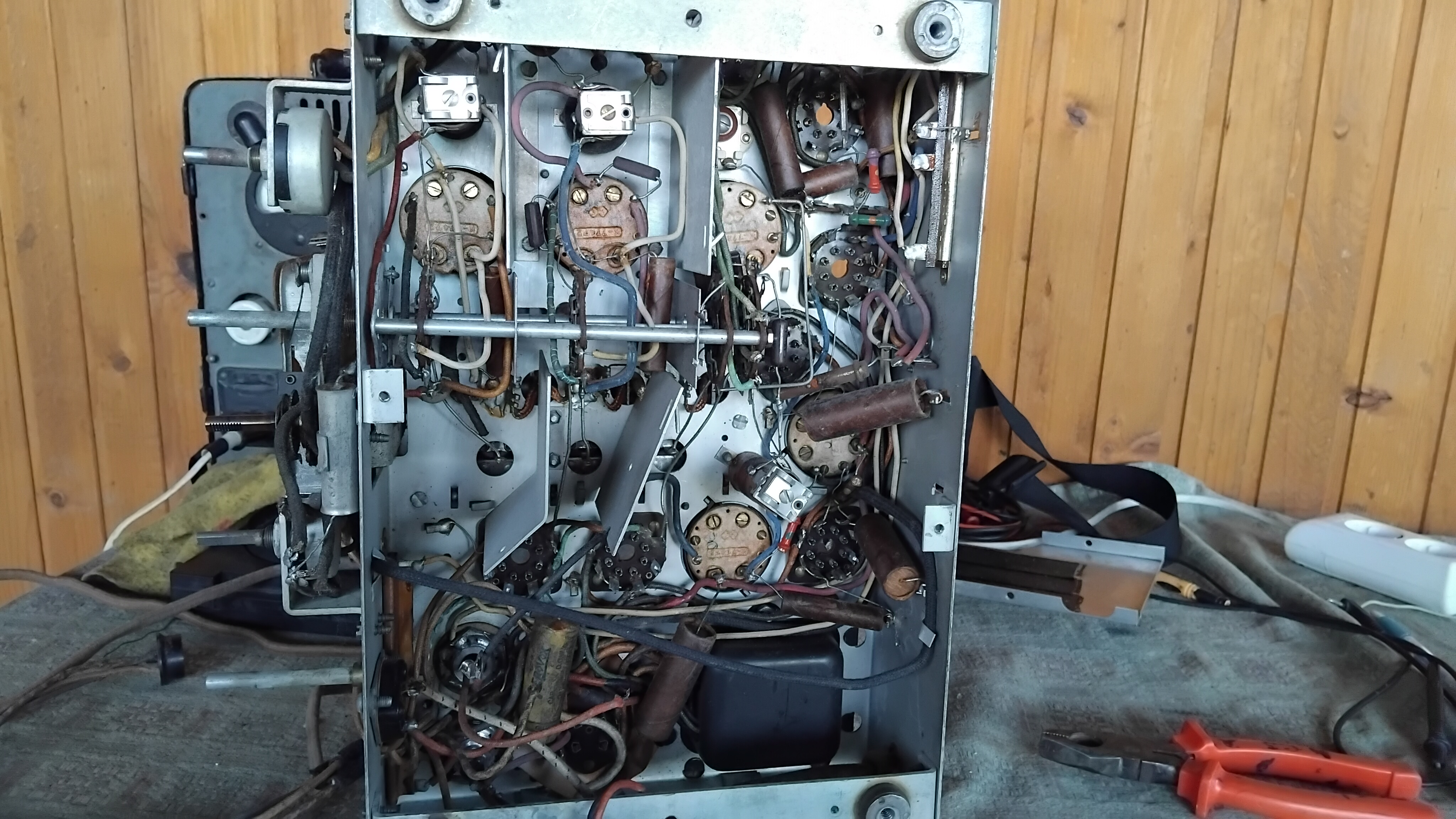
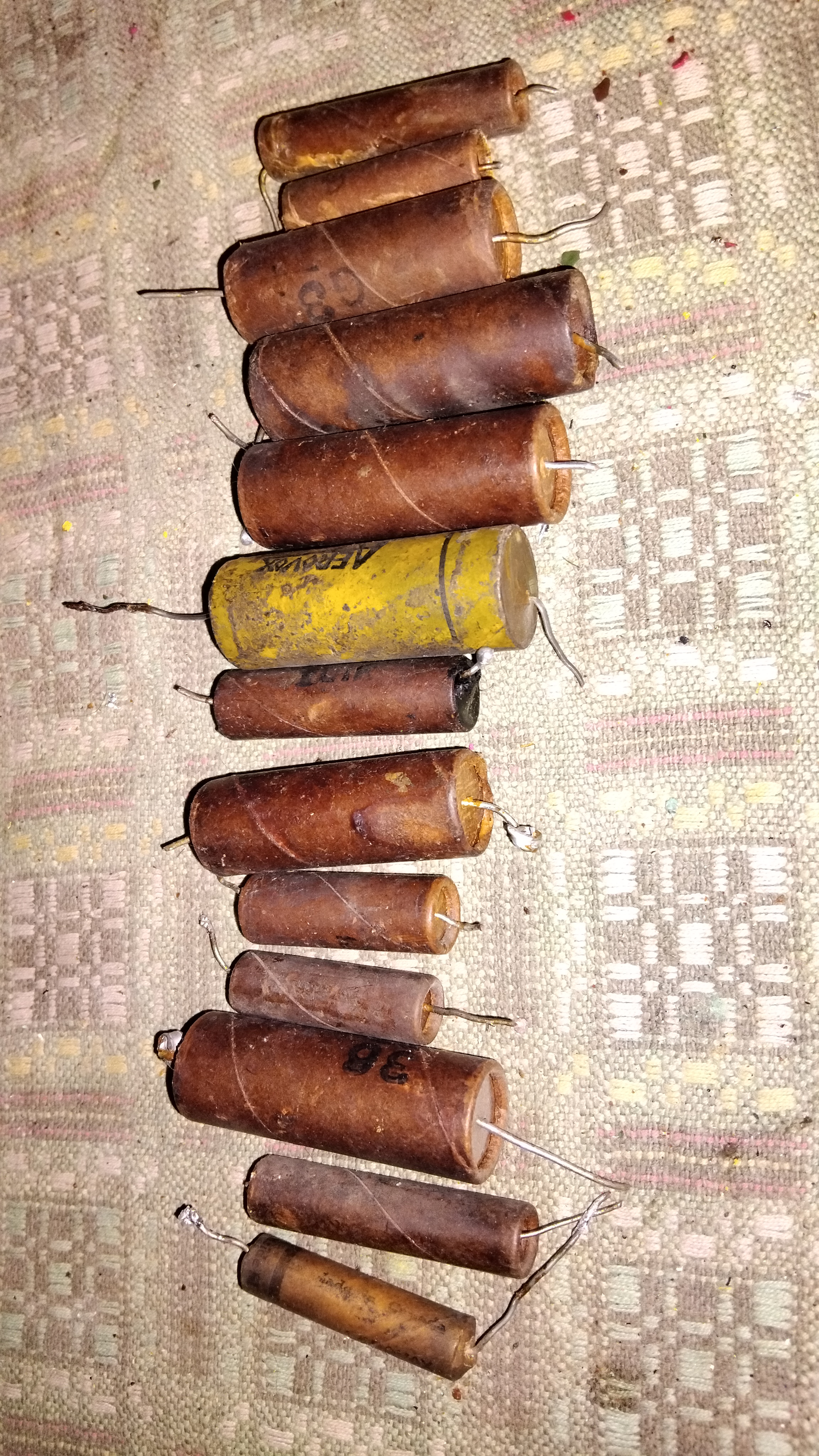
Of course I started by replacing the paper and electrolytic capacitors...
Old tube radios and gramophones museum TV channel
https://www.youtube.com/user/RadioSvit
Sincerely Peter
З повагою Петро
(This post was last modified: 06-18-2025, 07:34 AM by RadioSvit.)
Posts: 746
Threads: 24
Joined: Nov 2014
City: Svalyava. Transkarpatia
State, Province, Country: Ukraine
I also checked all the radio tubes on my Hickok 530 tube tester. The 5Z3 kenotron turned out to be faulty, all the other radio tubes are good.
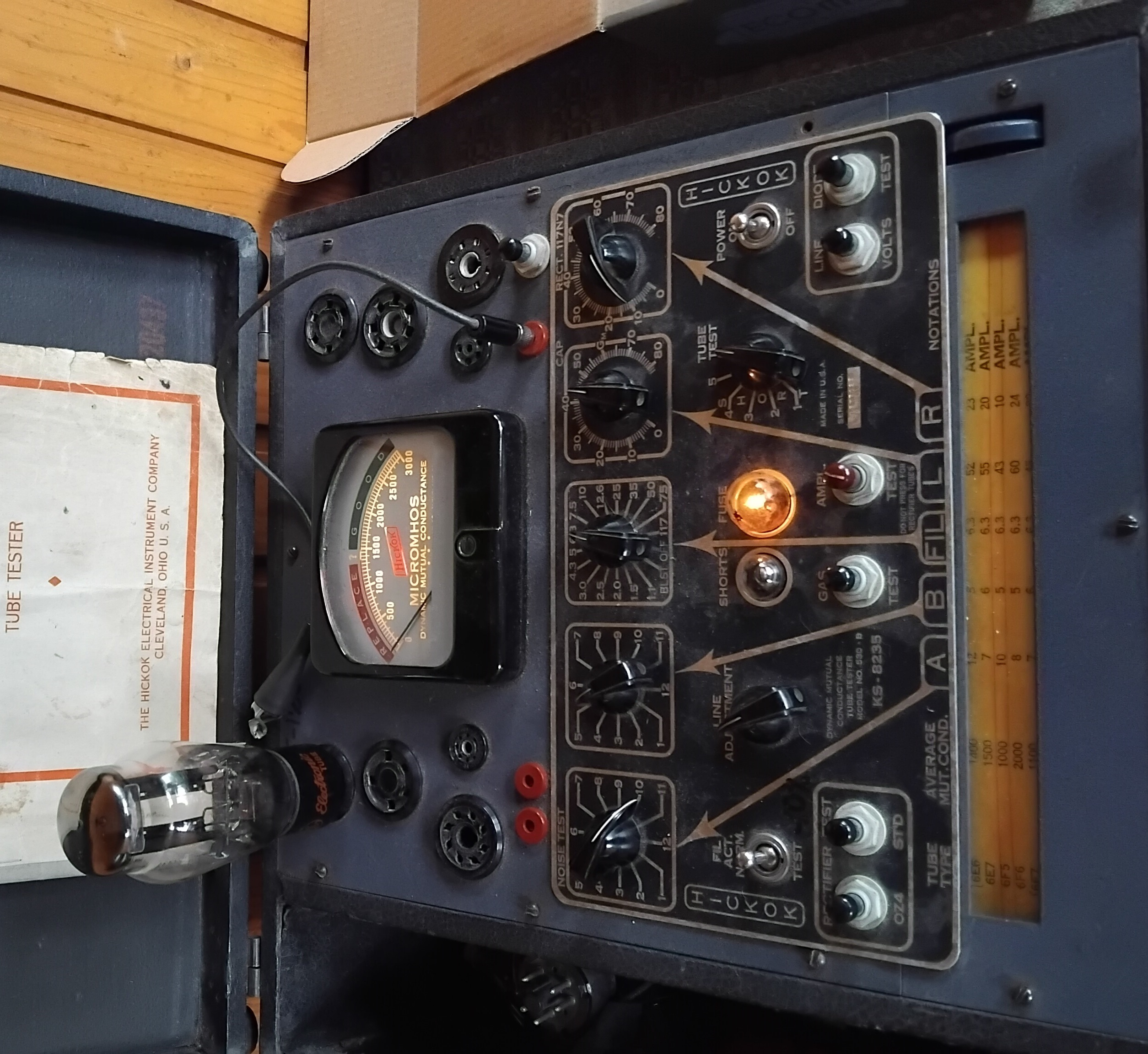
True, attentive readers will immediately see my mistake - when I took the photo, I forgot to switch the tester settings to the 5Z3 measurement mode and the settings remained on the measurement of the previous 6f5 pentode radio tube.
The problem with the 5Z3 box turned out to be more complicated than I thought - I don't have it. But there are many Soviet analogues of the 5Z3, but with octal sockets. So I had to replace the 4-pin socket with an octal one.
It was ...
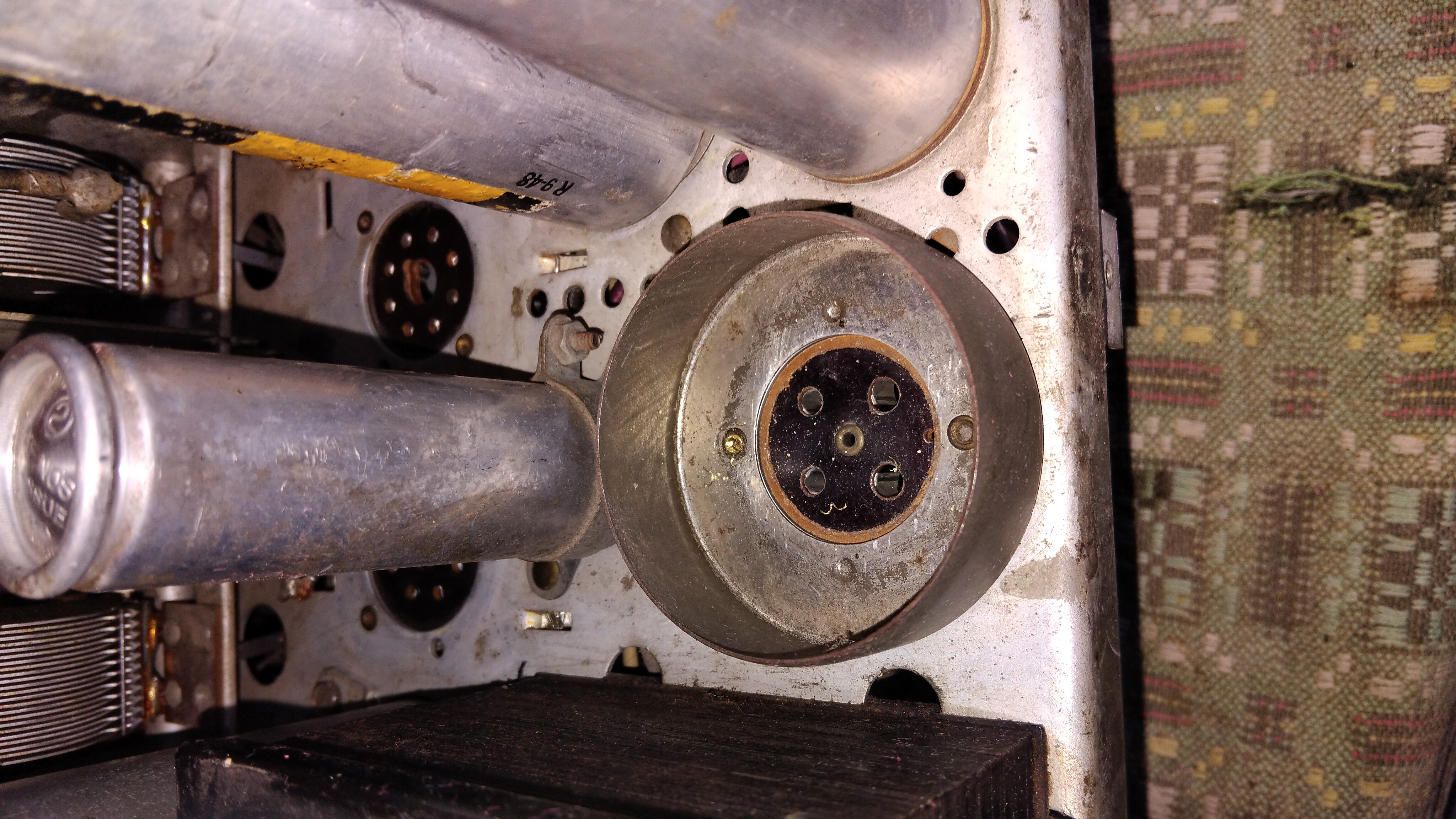
It became ...
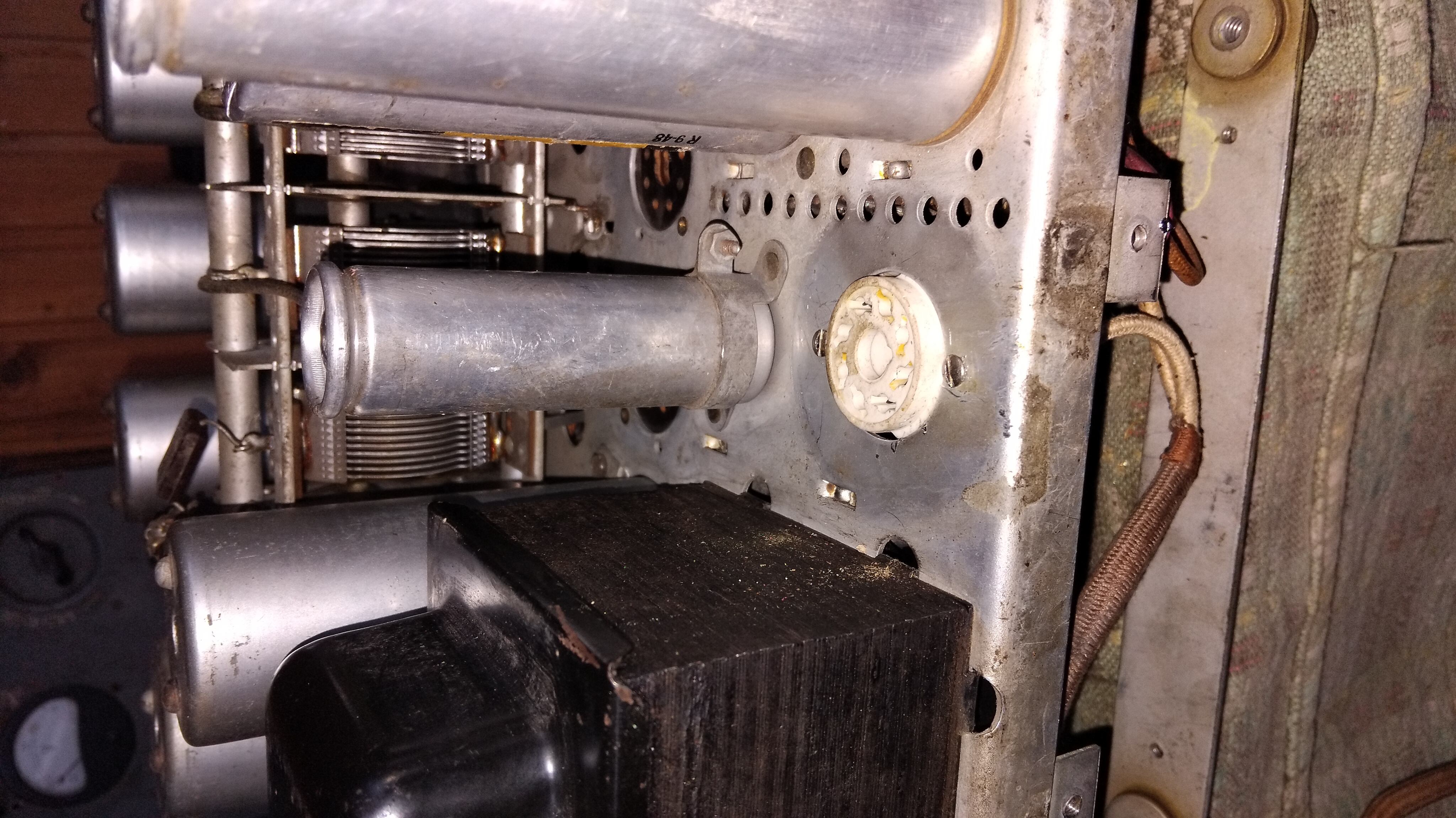
I also filmed the process of checking the radio tubes
[Video: https://www.youtube.com/watch?v=bZIAcVzJ3TM&t=12s]
Old tube radios and gramophones museum TV channel
https://www.youtube.com/user/RadioSvit
Sincerely Peter
З повагою Петро
(This post was last modified: 06-18-2025, 08:07 AM by RadioSvit.)
Posts: 18,427
Threads: 622
Joined: Oct 2011
City: Jackson
State, Province, Country: NJ
Great job on the cabinet.
PS. In the US notation, "kenotron" refers to specific type of tubes; we call regular rectifier tubes just that, "rectifier tube".
I understand this (being from the USSR myself), but many folks will not know what a kenotron is.
People who do not drink, do not smoke, do not eat red meat will one day feel really stupid lying there and dying from nothing.
Posts: 746
Threads: 24
Joined: Nov 2014
City: Svalyava. Transkarpatia
State, Province, Country: Ukraine
Thanks for your help Michael. In fact, this video is only an intermediate result. Later I had to apply another tinting layer of "Walnut" varnish to even out the shades of the facade, top cover and side walls. But I haven't created this final video yet, I plan to do it this week.
Old tube radios and gramophones museum TV channel
https://www.youtube.com/user/RadioSvit
Sincerely Peter
З повагою Петро
Posts: 5,654
Threads: 56
Joined: Sep 2008
City: Sandwick, BC, CA
Peter;
I think that I would have been more inclined just to make a 4 pin to octal adapter out of the base of the 5Z3 tube, we have an odd rectifier tube/kenotron that Rogers made here called a 2X3, and it is half of a 5Y3, both in pinout, and electrically, so you need to make adapters, or change sockets for those. They used pairs of octal sockets but Rogers removed the contacts from the sockets that were not needed for the 2X3s, so you can't put a 5Y3 or 5Y4 in there just by rewiring one of the sockets. I'm surprised that the C.G.E A-87 used a 5Z3, a type #80 or 5Z4 would have been more common then, a 5Z3 is like a four pin 5U4, which was normally used in larger sets with push pull output tubes.
That type of paper capacitor, with the rolled over ends, is one of the easier types to restuff, if original appearance is important. You can get the capacitor out by placing a mechanic's socket, of appropriate size on the bench, place one end of the capacitor on top of the socket, grasp the body of the paper tube, press down over the socket, and the inner part will pop out of the top.
Regards
Arran
Posts: 14
Threads: 2
Joined: Mar 2021
City: Milwaukee
State, Province, Country: Wisconsin
Arran this set is mechanically identical to the US RCA Victor T8-14 and C8-15, and yes, they chose the 5Z3 rather than an 80. It should actually have had a 5Z4 but it appears that Radiotron could not get enough of those produced to supply both US GE’s and RCA Victor’s needs.
When RCA Victor first rolled out its 1936 line it had four metal tube chassis in it - this one, the 10/11 tube chassis, the 13 tube chassis and the 15 tube chassis. The line had no midrange volume-model radios until just before Christmas, just high end sets and cheap glass-tube midgets and farm sets. I remember hearing somewhere that this was because of the poor production yield for 6A8 tubes. Anyway, since the bigger chassis all required a 5Z3 (hidden in a black metal can so that nobody saw glass in what was supposed to be an all-metal-tube set), it seems apparent that they just kept it the same in the 8-tube chassis for ease of manufacturing.
(This post was last modified: 06-18-2025, 11:24 PM by pdieten.)
Posts: 746
Threads: 24
Joined: Nov 2014
City: Svalyava. Transkarpatia
State, Province, Country: Ukraine
Arran , pdieten... Guys, I am also very surprised that a rectifier radio tube with three times more power than is enough for this circuit is used here. A rectifier radio tube of type 80 or 5Z4 is really more than enough here. But they are also 4-pin and in Ukraine are extremely rare and expensive. But we have many Soviet analogues of these radio tubes with an 8-pin base here. So that is why I replaced the 4-pin socket with an 8-pin one and then I will be able to use the Soviet analogues of 5Z4 without any problems. Today I am finishing the chassis repair and in the near future I will show the final photos after the repair
Old tube radios and gramophones museum TV channel
https://www.youtube.com/user/RadioSvit
Sincerely Peter
З повагою Петро
Posts: 1,797
Threads: 55
Joined: Feb 2015
City: Roseville, MN
Simple fix, Peter. Less heat also. So far you have a Canadian Soviet GE RCA.
(This post was last modified: 06-19-2025, 04:48 PM by RodB.)
Posts: 746
Threads: 24
Joined: Nov 2014
City: Svalyava. Transkarpatia
State, Province, Country: Ukraine
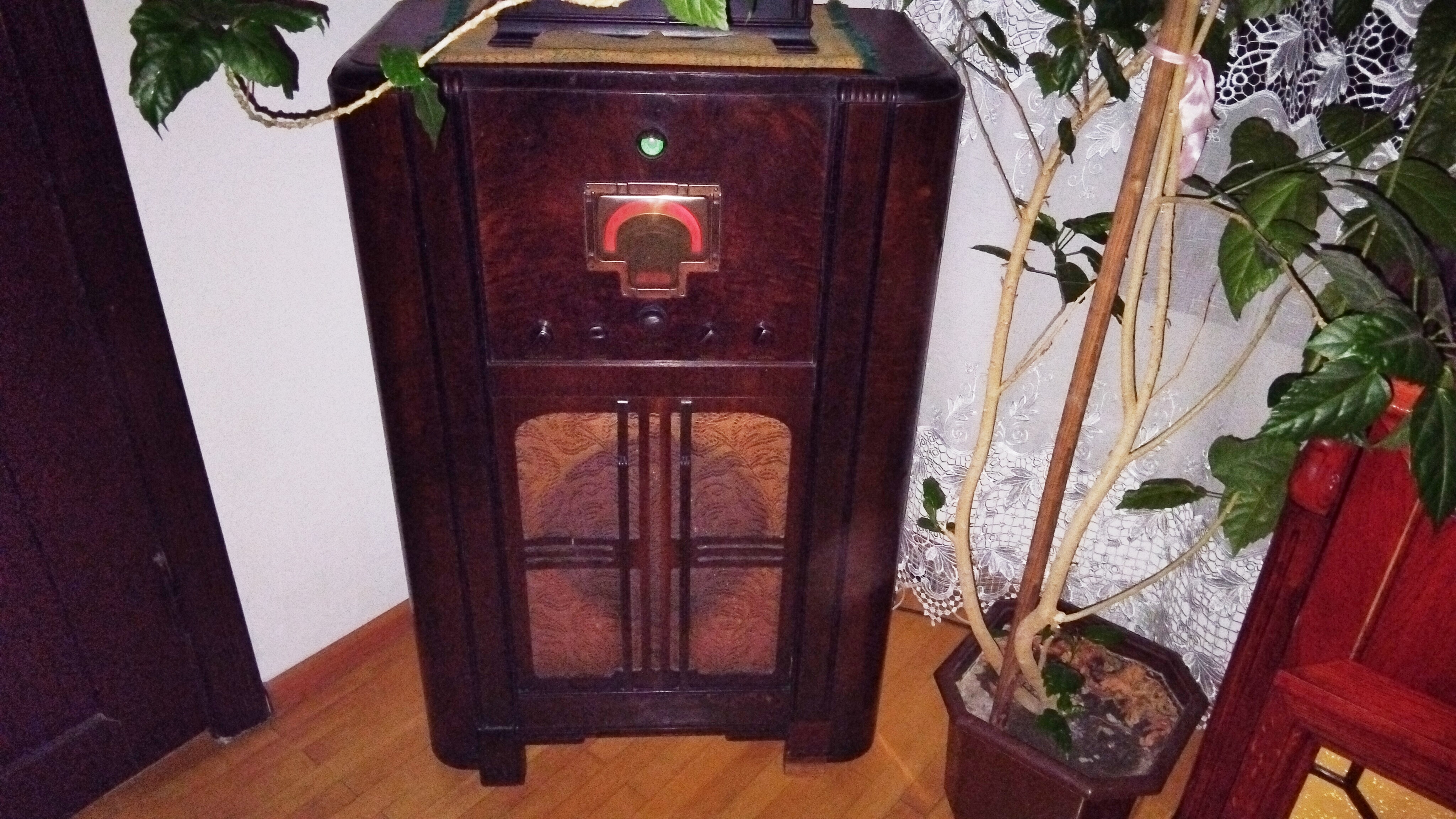
Thanks, RodB. Actually, I have my own pure American RCA 9K and I like it much better than this General Electric. And RCA has great reception and sound.
Old tube radios and gramophones museum TV channel
https://www.youtube.com/user/RadioSvit
Sincerely Peter
З повагою Петро
Posts: 14
Threads: 2
Joined: Mar 2021
City: Milwaukee
State, Province, Country: Wisconsin
There’s nothing wrong with switching to an octal socket for a 5Z4. Typically if I’m restoring a set like this I try to reinstall the shield base and shield to retain the original topside appearance. But if that isn’t possible, then so be it.
The 9T is a better radio than the 8-tube set you’re working on. There’s nothing wrong with the 8-tube set, it just doesn’t have the technical advances that RCA developed for the 9T because the 9T is a year newer.
(This post was last modified: 06-21-2025, 12:39 AM by pdieten.)
Users browsing this thread: 1 Guest(s)
|
|
Recent Posts
|
|
Stromberg Carlson 1500 Squeal
|
| And life just keeps getting more complicated. By dconant.
Dittos'Jimradio — 08:01 AM |
|
Plug Voltages Needed For A 1943 CRV-20130 Power Supply
|
| That looks a lot like an aircraft connector of some kind, even if it's a U.S.N power supply. I have a book somewhere abo...Arran — 02:56 AM |
|
Plug Voltages Needed For A 1943 CRV-20130 Power Supply
|
| hello david,
I have a similar generator in my collection that features a cast iron, single-cylinder Briggs & Stratt...radiorich — 01:00 AM |
|
under chassis parts locator diagram for 1938 Zenith 9s262
|
| Has anyone gone to the trouble of creating an under chassis parts locator image? Yes, I can identify components by foll...bobloney — 08:57 PM |
|
Plug Voltages Needed For A 1943 CRV-20130 Power Supply
|
| Try looking at this site the book mark is for a old generator that I was given. David https://radionerds.com/index.ph...David — 08:36 PM |
|
Plug Voltages Needed For A 1943 CRV-20130 Power Supply
|
| Hello Everyone,
I am looking for voltage identification for all the pin positions on the socket of a CRV-20130 power su...Tonym4704 — 08:16 PM |
|
Philco P45-6365 Universal Transformer Instruction Manual
|
| Can anyone guide me to where this may be found?GRG — 03:00 PM |
|
54C Complete Teardown/Rebuild
|
| I don't think that I have encountered a 12Z3 before, curious how it uses one of those but includes a #43, which is a 25 ...Arran — 02:17 PM |
|
HiFi (Chifi) tube amp build - but my own design.
|
| It's the other forum. I'm also in DIY, but mostly read there. Honestly, I kinda jumped into this without much thought to...TV MAN — 10:43 AM |
|
Philco 71 Code 125
|
| Hello,
I am in need of a schematic for this radio. Mine has the three separate circular tube shields and a shadow me...dconant — 08:06 AM |
|
Who's Online
|
There are currently 2252 online users. [Complete List]
» 1 Member(s) | 2251 Guest(s)
|
|
|

|
 
|








