Posts: 18,427
Threads: 622
Joined: Oct 2011
City: Jackson
State, Province, Country: NJ
Gathering info at this point.
Watched a video on an AK10 restoration. Over 1hr.
So, I need to get a power supply. I could likely make it (it is a 0.25A per tube filamengt current, 5 tubes total), 45V and 90V.
Easy. But will need to make a board and get a case. Also will need a transformer as I think this is not the best case for a switcher.
If those are sold for reasonable price, I could swallow my professional pride and buy one.
I know., Ron wrote he intended this as a shelf queen.
But I think he'd be pleased to know it was restored.
The start will depend on how much info I can get and how much work it will be requiring to be repaired.
There are transformers that go open and are potted with some tar, etc etc.
I do not intend to refinish it.
I also have a round pedestal AK speaker. It might work. I was told it is a functional speaker.
Of course, a horn would look better.
People who do not drink, do not smoke, do not eat red meat will one day feel really stupid lying there and dying from nothing.
Posts: 5,655
Threads: 56
Joined: Sep 2008
City: Sandwick, BC, CA
Mike;
You could use a power transformer from a junked AC radio chassis to supply most of what you need for a power supply. I'm surprised it doesn't have a 135 volt input, they liked to use those for the audio stages. The speaker is easy to test, a 9 volt battery across the leads, if it clicks it's good, if not the cord might be bad. I think the horn you will want is a model "M" AK speaker, at least if you really want to stick with an A.K horn, and not a Magnavox, Music Master, or some other type.
Regards
Arran
Posts: 3,189
Threads: 226
Joined: May 2008
City: Omak
State, Province, Country: WA
Hello morzh,
There is a gentlemen on ARF forum and facebook named David who has worked on a lot AK sets I will give him the link to this post .
Sincerely Richard
P.S. Ron would be pleased to see it work !
Posts: 34
Threads: 9
Joined: Jul 2008
City: Bossier City, LA
Yes, you will require a power supply. This set has no need for 135 volts, as it does not utilize a power tube. This set utilizes all O1A tubes. I highly recommend the Arbe III power supply.
yes, the most common fault is bad audio transformers. They can easily be checked without removing top cover. As far as the tar---freeze it! If one has to change audios, place can, with cover removed in freezer overnight. Next day invert can and smack on smooth concrete and the tar will crumble and pop out clean!
Arbe make great replacement transformers, as well as a great supply.
Posts: 18,427
Threads: 622
Joined: Oct 2011
City: Jackson
State, Province, Country: NJ
Thanks guys, very helpful.
I will check out Arbe.
People who do not drink, do not smoke, do not eat red meat will one day feel really stupid lying there and dying from nothing.
Posts: 18,427
Threads: 622
Joined: Oct 2011
City: Jackson
State, Province, Country: NJ
I just ordered ARBE III.
I mean, it is a good unit, and, being honest, I cannot see how these guys can make any money selling these for what they sell them.
If I were to embark on a mission of building one myself - and I am an EE, with plenty of experience to build such a supply from scratch - I would probably pay at least twice what I pay to them.
First time ordering a PCB, in small quantity, the PCB will be at least 25-40 bucks itself.
A box.
A heatsink.
Parts from Mouser, again, in small qty.
A transformer.
And then drilling, wiring. Honestly, this is not a project I'd consider fun. A mundane, mostly parametric transformer power supply. Boring. Like driving a historic car. It is fun, but you have to gas it up, and while necessary, there is no fun in gassing up.
So. If only to support the guy.
PS. I have not bought the battery case. In teh future if I decide i want it, I'll buy it.
People who do not drink, do not smoke, do not eat red meat will one day feel really stupid lying there and dying from nothing.
Posts: 5,655
Threads: 56
Joined: Sep 2008
City: Sandwick, BC, CA
Mike;
One of the restoration channels I occasionally watch (electronics old and new) is sponsored by an outfit called "PCB Way" I don't have an opinion of them but their rates seem inexpensive should I have a need to make printed circuit boards, I think that five boards is their minimum order. On the other hand I'm pretty sure they are located in Asia somewhere. I've known of people who have made their own P.C boards, with the chemicals and stuff, but I never have, I always used point to point wiring since everything I tried building was higher voltage, and linear.
The iron (transformers) is what gets expensive, which is why I've tried to repurpose ones salvaged from something else. I need to make a step up supply for a British Kolster-Brandes radio I acquired, I found a ballast for a metal halide lamp will be more then adequate, the one I have is an autotransformer, but some do have proper primaries and secondaries, the thing is rated for 8 amps. Battery tube radio power supplies, whilst you can use a proper heat sink for the regulators, you can also use a piece of scrap metal as a heat sink, though I have enough proper ones that I have salvaged from scrapped amps and computer power supplies.
Regards
Arran
Posts: 18,427
Threads: 622
Joined: Oct 2011
City: Jackson
State, Province, Country: NJ
Arran
I was making my own PCBs back in the old country ever since I was 13.
The one-sided laminate (first it was a phenolic paper one; then came fiberglass) or, eventually, in 80s, 2-sided; Mom's nail polish, then Fe-Cl3 (Ferric Chloride) that I somehow was able to get.
Here in the US, around 1990 I used photo-sensitized laminate, printed the artwork on a transparency; exposed to sunlight, then etched the resist in baking soda solution, then again Fe-Cl3.
This is great, but for double-sided board I'd have to use those via eyelets, solderabled, that would be inserted and flared in a through-hole.
Messy, long. A kit also added to cost.
I still can do it in my sleep, even though igt's been 35 years since. But...why?
People who do not drink, do not smoke, do not eat red meat will one day feel really stupid lying there and dying from nothing.
Posts: 5,655
Threads: 56
Joined: Sep 2008
City: Sandwick, BC, CA
Mike;
As I was saying, the stuff I was making was linear, so point to point was perfectly fine, and making a P.C board seemed pointless given that these were one off projects mostly made out of salvaged stuff. Many of the electronics magazines from the 80s and 90s had build projects where making the P.C board was half the project, usually something involving one I.C or another that I had no interest in. Another thing some guys used was perf board, but that isn't that cheap either.
I was thinking that PCB Way outfit might be useful if one had something like a board out of a vintage TV, or amp, where the original board was badly damaged, cracked, burned, or where the traces were falling off, apparently they can make boards out of a similar phenolic material, and drill them for you as well. I had a Sylvania AC/DC radio where a good part of the ground plain was just falling off the edge of the board, I repaired it, and then passed it on as it was from the late 1950s anyhow. There was a good reason why Brand Z swore off using P.C boards for so long, the early ones were often horrible, though they did compromise on it in their transistor radios by the 60s, not in the T.O models however.
Regards
Arran
Posts: 18,427
Threads: 622
Joined: Oct 2011
City: Jackson
State, Province, Country: NJ
Yeah. The 60-s and 70-s All-wave radios from Russia (VEF was the famous one) used those 1-sided phenolic PCBs. They survive very well, but not repair-friendly.
However if you remember that fiasco of me helping that blind guy here with TPA-1 Philco portable record player, they had that phenolic PCB, and everything that weighed anything and had through pins, especially the output transistors, ended up separating the traced from the substrate (and the traces were fairly wide) and eventually ripping them.
Bad design. A portable unit, subject to vibration and jolts, these transistors should've been at least glued or put on those spacers.
People who do not drink, do not smoke, do not eat red meat will one day feel really stupid lying there and dying from nothing.
Posts: 18,427
Threads: 622
Joined: Oct 2011
City: Jackson
State, Province, Country: NJ
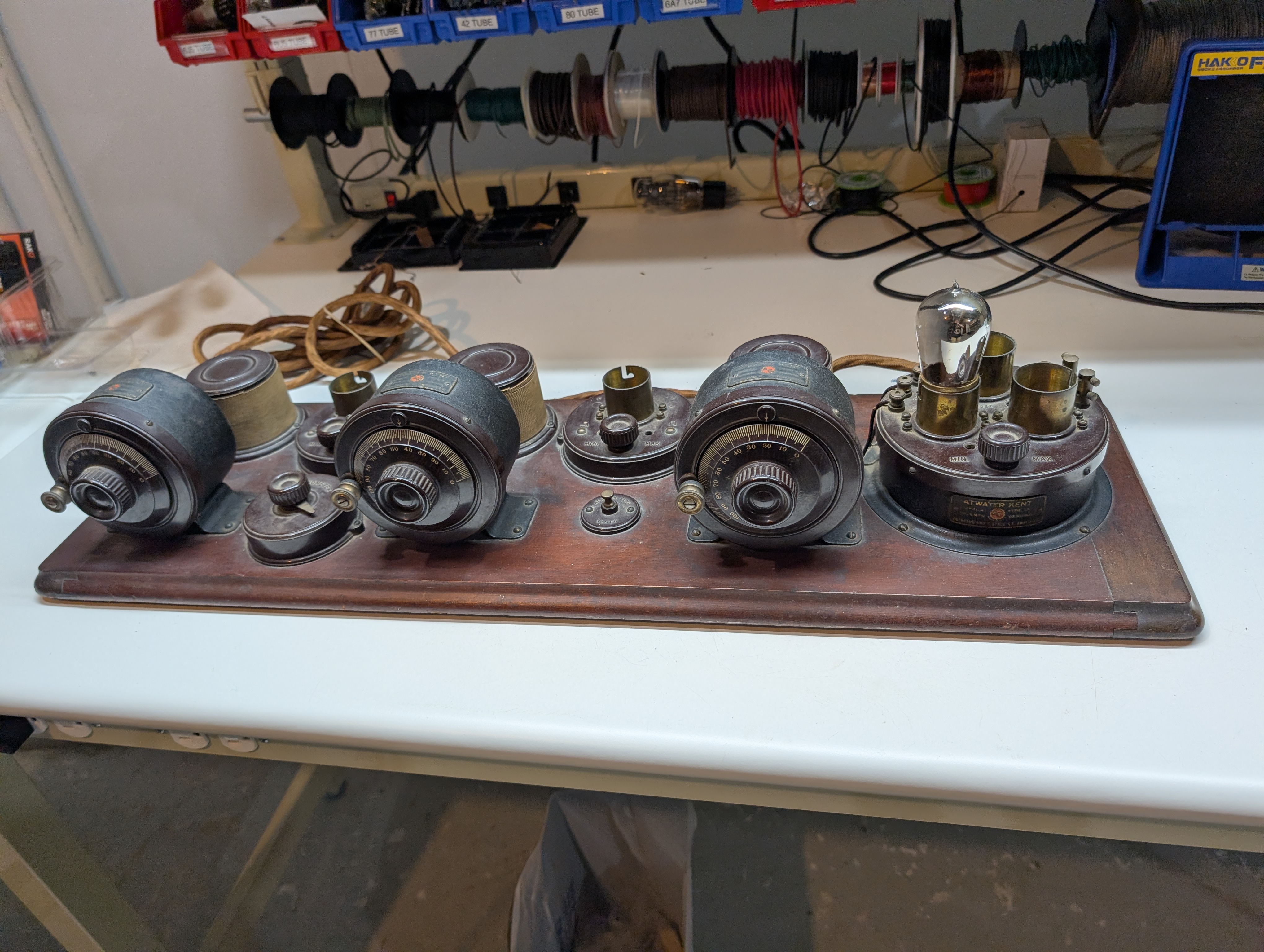
This is how it looks before the taking apart commences.
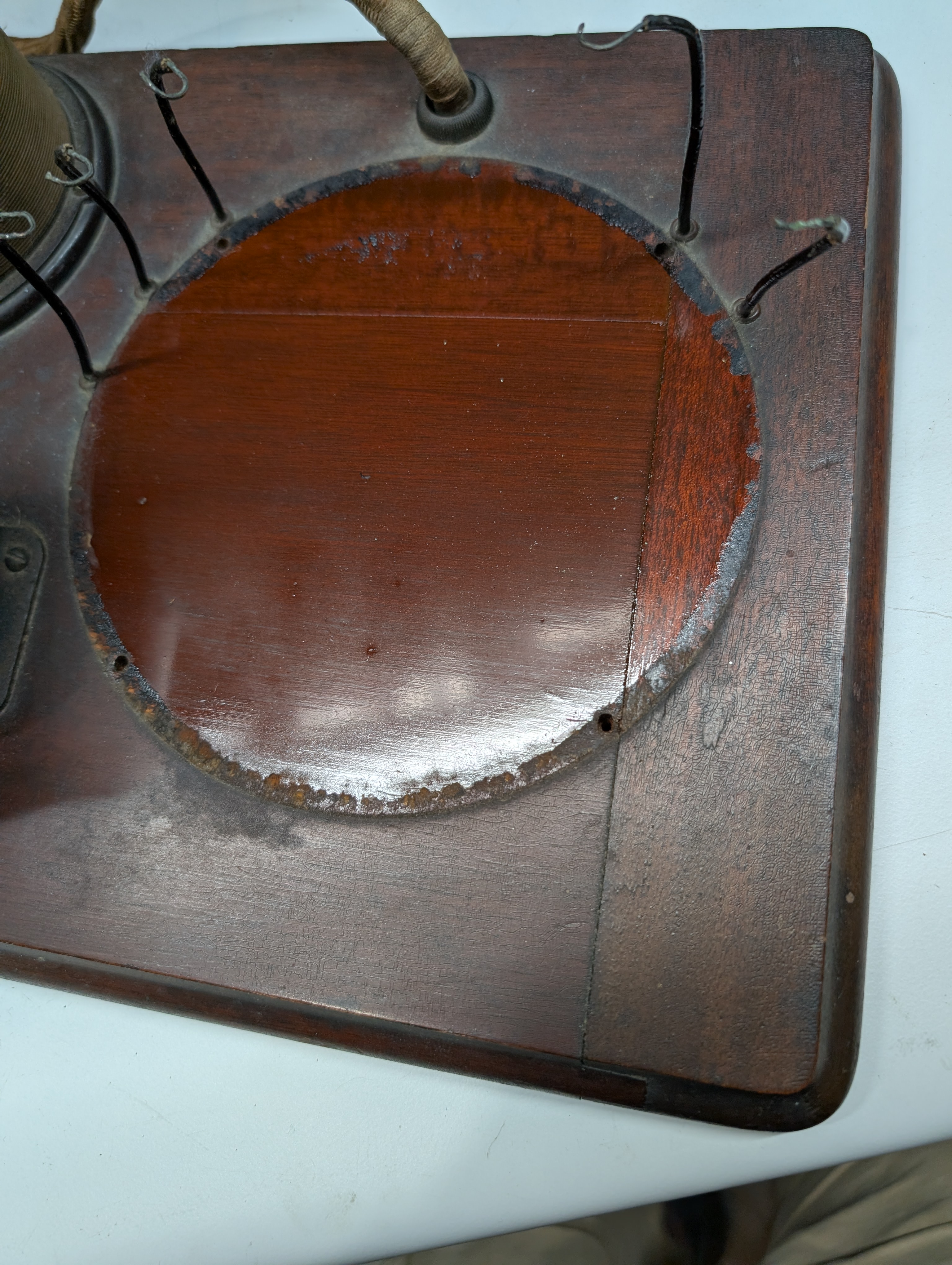
I took the amp assy off.
This is what the original finish looked like.
Now, this is the schematic for reference.
The first audio transformer is good.
The second has its primary open.
I am not sure it is easy to save one transformer and remove the other.
Will probably have to replace both.
People who do not drink, do not smoke, do not eat red meat will one day feel really stupid lying there and dying from nothing.
Posts: 18,427
Threads: 622
Joined: Oct 2011
City: Jackson
State, Province, Country: NJ
So, here's another question.
The original tubes here have bayonet base.
The UX201 John got for me (5 out of 6 are good, and i need 5) have regular UX base, and that has long pins and no bayonet.
I guess, I need some sort of UX-to-UV adaptor.
Short of making those myself from old bad UV tubes...where do I get'em?
People who do not drink, do not smoke, do not eat red meat will one day feel really stupid lying there and dying from nothing.
Posts: 181
Threads: 7
Joined: Apr 2025
City: SPRUCE GROVE
State, Province, Country: Alberta
If you want to work, lie down and sleep, and everything will pass.
Posts: 18,427
Threads: 622
Joined: Oct 2011
City: Jackson
State, Province, Country: NJ
Thanx, Vlad.
Looking at it (yes it does say "UX4 to UV4"), I am not sure how it works.
It has long pins and no bayonet side pin.
I guess I will have to ask them.
I guess, worst case, I have those 5 UV duds. I could remove the envelopes, buy those porcelain round 4-pin sockets and make the adapters.
People who do not drink, do not smoke, do not eat red meat will one day feel really stupid lying there and dying from nothing.
Posts: 5,655
Threads: 56
Joined: Sep 2008
City: Sandwick, BC, CA
Mike,
The bayonet based '01As are not like UX199s compared to UV199s, where they have different pinouts, they are the same electrically as the UV versions, just with longer pins. in fact many sets in the 1924-25 era had bayonet sockets, but they left the dealer with UV201As in them, with the locking pin. I'm not sure when they discontinued making UX based tubes, but I read that A.K quit using them because the four pin UV style sockets were cheaper, so the late model 20C sets had four pin sockets like an #80 would use, the one I inherited from my late uncle used bayonet style sockets, but with UV tubes in the sockets, including some ST style '01As, again with the side pin.
Regards
Arran
Users browsing this thread: 6 Guest(s)
|
|
Recent Posts
|
|
Philco 71 Code 125
|
| Looks like that might be the B- buss, so that would be correct.RodB — 01:32 PM |
|
Philco 71 Code 125
|
| I noticed on the code 121 schematic the center tap for the 6 volt winding and hv winding are tied together. Is this corr...dconant — 12:16 PM |
|
Philco 45-6365 Universal IFT Instruction Manual
|
| The Philco Parts Catalog for 1942 shows it as usable for 175 kHz, 260 kHz, and 465 kHz. The instructions will show how t...DaleHCook — 11:19 AM |
|
Stromberg Carlson 1500 Squeal
|
| Hello Rob,
I agree with you—I have one here at my house that I need to check out. It’s way over-engineered just to make...radiorich — 11:05 AM |
|
My Atwater Kent 84
|
| Well getting around to restoring my AK84. Mike was a big part in me being able to snatch this one a few years ago. I won...462ron — 10:57 AM |
|
Plug Voltages Needed For A 1943 CRV-20130 Power Supply
|
| The engine is a B&S 23 inch cast Iron holds 2 quarts of oil. The Generator is a 4 pole 1800 rpm mine was made in 195...David — 10:51 AM |
|
Philco 45-6365 Universal IFT Instruction Manual
|
| Dale: Modified topic as suggested. It is not for a specific project. I found it in a box of stuff I recently purchased...GRG — 10:34 AM |
|
Plug Voltages Needed For A 1943 CRV-20130 Power Supply
|
|
That looks a lot like an aircraft connector of some kind ...
That is a MIL-5015 style connector, used in a wide v...DaleHCook — 10:19 AM |
|
Philco P45-6365 Universal Transformer Instruction Manual
|
| I would suggest changing the topic from "P45-6365 Universal Transformer" to "45-6365 Universal IFT."...DaleHCook — 10:08 AM |
|
Stromberg Carlson 1500 Squeal
|
| And life just keeps getting more complicated. By dconant.
Dittos'Jimradio — 08:01 AM |
|
Who's Online
|
There are currently 1492 online users. [Complete List]
» 1 Member(s) | 1491 Guest(s)
|
|
|

|
 
|







