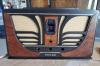
Philco 53-958 selenium rectifier
Posts: 711
Threads: 46
Joined: Sep 2009
City: Lapeer, MI
State, Province, Country: USA
Confused again.  I need to replace the selenium rectifier in this radio. Have to drop 10V using a 1N4007. Using the formula R = Vdrop/IDC = 10 V/0.375 A = 27 ohms. Calculating wattage, P = V2/R = 100/27 = 3.7 watts I have 22 ohm and 3.5 ohm resistors each 5 Watt for a total of 25.5 ohms. Close enough on resistance. I'm not sure about the wattage. Will combining these in series work safely, or will one resistor carry too much of the current? Thanks, Joe
Courage will follow when Faith takes the lead.
(This post was last modified: 07-04-2026, 07:51 PM by Joe Rossi.)
Posts: 2,327
Threads: 23
Joined: Jul 2020
City: Greenlawn
State, Province, Country: NY
Ni Joe,
In a series circuit, current is constant. In your example, the current is 0.375A anywhere in the series circuit. If P = EI (Wattage = Voltage X Current), then, like you said, the total dissipated power through the 27 Ohms is 3.7W, However, since you have a 22 Ohm and a 3.5 Ohm resistor, the current through each is the same, but the 22 Ohm resistor will dissipate more power than the 3.5 Ohm resistor. There is absolutely no problem with the 3.5 Ohm resistor. The 22 Ohm one will dissipate more because the voltage drop across that resistor is much more than the voltage drop across the 3.5 Ohm resistor. However, you are safe. I would feel a little better if the 22 Ohm resistor was a 10 watt job but you are still OK here.
"Do Justly, love Mercy and walk humbly with your God"- Micah 6:8
"Let us begin to do good"- St. Francis
Best Regards,
MrFixr55
Posts: 18,427
Threads: 622
Joined: Oct 2011
City: Jackson
State, Province, Country: NJ
What John said.
My rule of rating wattage is at least double. The smaller it is, the hotter it will get.
People who do not drink, do not smoke, do not eat red meat will one day feel really stupid lying there and dying from nothing.
Posts: 711
Threads: 46
Joined: Sep 2009
City: Lapeer, MI
State, Province, Country: USA
Gentlemen, Thank you as always! I try to use what is to hand, and I have three 100-Ohm resistors, which will give me 33-Ohms in parallel. Resistance is close enough and
I have two 20-Watt and one 15-Watt resistors. Now all I have to do is find room... Thanks again, Joe
Courage will follow when Faith takes the lead.
Posts: 1,798
Threads: 55
Joined: Feb 2015
City: Roseville, MN
Joe,
You could place them strategically around the chassis so they can make the chassis warm enough to keep your coffee hot.
Posts: 18,427
Threads: 622
Joined: Oct 2011
City: Jackson
State, Province, Country: NJ
yeah, those are some sizeabe resistors.
People who do not drink, do not smoke, do not eat red meat will one day feel really stupid lying there and dying from nothing.
Posts: 711
Threads: 46
Joined: Sep 2009
City: Lapeer, MI
State, Province, Country: USA
Maybe I could saw them in half and make 10 Watt resistors? Actually, a through-hole for the wires going to the selenium will be available now. I can use a tie-wrap hold them firm to the chassis. Then I can place the chassis on its side and use it to keep my coffee warm. Problem solved! 
Joe
Courage will follow when Faith takes the lead.
Posts: 1,136
Threads: 55
Joined: Feb 2013
City: Shenandoah,
State, Province, Country: Pennsylvania
Gentlemen, just a thought here. Being that this is a tube radio and tubes are fairly robust, is it worth worrying about an extra 10V B+ ? I pondered this question sometime back when restoring my Zenith AM/FM table top radio when I replaced the selenium rectifier with a silicon diode. There already was a 22 ohm resistor there to limit surge current to the first electrolytic so I basically just swapped out the selenium for a silicon diode. This radio is my daily driver in my shop and has been playing just fine for well over a year now. That extra 10V isn’t even 10% extra, well within the tolerance of what is expected on the schematic. Thoughts!!
Ron
Bendix 0626. RCA T64 Philco 20B
Philco 41-250. Philco49-500
GE 201. Philco 39-25
Motorola 61X13. Philco 46-420 Crosley 52TQ
Philco 37-116. Philco 70
AK 35 Philco 46-350
Philco 620B. Zenith Transoceanic B-600
Philco 60B. Majestic 50
Philco 52-944. AK 84
Posts: 18,427
Threads: 622
Joined: Oct 2011
City: Jackson
State, Province, Country: NJ
As long as this is strictly B+, I guess it is not that bad.
However you also have to take into account the fact that the Mains voltage is higher than it used to be by up to 15V (116-124VAC vs 105-110VAC back then).
Go by the datasheet; if the resulting voltage is up about 25-30VDC from all factors combined, I would tru to bring it down as this is up to 25-30% from the previous one, meaning the same percentage of the dissipated power. While tubes will take that (they obviously were not used at the upper limit of the plate voltage), this rise in dissipated power will shorten their life.
So if it is the daily driver, that's one thing; if it is a demo unit you turn on once in a while, its another thing.
People who do not drink, do not smoke, do not eat red meat will one day feel really stupid lying there and dying from nothing.
Posts: 1,422
Threads: 41
Joined: Jan 2014
City: Wellborn Florida
Alone with adding a dropping resistor after the 1n4007 to help out the heaters change the output tube from a 35C5 to a 50C5. David
Posts: 18,427
Threads: 622
Joined: Oct 2011
City: Jackson
State, Province, Country: NJ
I think the filaments are OK as is.
The sum of all filaments voltages plus three resistors (130 Ohms when the NTC tube saver warms up) is 124V.
Which is good for even the high end of today's AC voltage.
People who do not drink, do not smoke, do not eat red meat will one day feel really stupid lying there and dying from nothing.
Posts: 1,798
Threads: 55
Joined: Feb 2015
City: Roseville, MN
Ron,
When FM is in the radio an extra ten volts might affect the front end. I did what you did for a Silvertone radio and the FM wouldn't come in because the B+ was too high. When I brought it back to what the schematic indicated it played fine.
Posts: 5,654
Threads: 56
Joined: Sep 2008
City: Sandwick, BC, CA
Given that this is basically an AC radio, and not a portable with battery tubes, I wouldn't worry too much about increased B+ voltage, however I would use two silicon diodes in series in case one of them decides to short, though the worst that may happen is destroying the filter caps if it does. If extra B+ is an issue to the FM front end you could add a dropper for the FM section, however I suspect that these sets were intended to operate over a fairly wide line voltage range. Personally I would use one of those chassis mounted resistors, or use a hollow wire wound mounted on a bolt for heat dissipation. Come to think of it you could put both the tube heaters and the B+ in series with the resistor, it would help the tubes live a bit longer, the question is what is your current power line voltage?
Regards
Arran
(This post was last modified: 07-06-2026, 07:37 PM by Arran.)
Posts: 18,427
Threads: 622
Joined: Oct 2011
City: Jackson
State, Province, Country: NJ
1N4007 is a 1000V / 1A (average) diode. The chances of it shorting while conducting...what is it again it is conducting? under a 100mA? and rectifying some 14% of its Vr? - the chances are not huge.
I love this one, BTW - one of the best most usable rectifier diodes made.
People who do not drink, do not smoke, do not eat red meat will one day feel really stupid lying there and dying from nothing.
Posts: 2,327
Threads: 23
Joined: Jul 2020
City: Greenlawn
State, Province, Country: NY
And DIRT CHEAP also!!
"Do Justly, love Mercy and walk humbly with your God"- Micah 6:8
"Let us begin to do good"- St. Francis
Best Regards,
MrFixr55
Users browsing this thread: 1 Guest(s)
|
|
Recent Posts
|
|
Philco 71 Code 125
|
| Looks like that might be the B- buss, so that would be correct.RodB — 01:32 PM |
|
Philco 71 Code 125
|
| I noticed on the code 121 schematic the center tap for the 6 volt winding and hv winding are tied together. Is this corr...dconant — 12:16 PM |
|
Philco 45-6365 Universal IFT Instruction Manual
|
| The Philco Parts Catalog for 1942 shows it as usable for 175 kHz, 260 kHz, and 465 kHz. The instructions will show how t...DaleHCook — 11:19 AM |
|
Stromberg Carlson 1500 Squeal
|
| Hello Rob,
I agree with you—I have one here at my house that I need to check out. It’s way over-engineered just to make...radiorich — 11:05 AM |
|
My Atwater Kent 84
|
| Well getting around to restoring my AK84. Mike was a big part in me being able to snatch this one a few years ago. I won...462ron — 10:57 AM |
|
Plug Voltages Needed For A 1943 CRV-20130 Power Supply
|
| The engine is a B&S 23 inch cast Iron holds 2 quarts of oil. The Generator is a 4 pole 1800 rpm mine was made in 195...David — 10:51 AM |
|
Philco 45-6365 Universal IFT Instruction Manual
|
| Dale: Modified topic as suggested. It is not for a specific project. I found it in a box of stuff I recently purchased...GRG — 10:34 AM |
|
Plug Voltages Needed For A 1943 CRV-20130 Power Supply
|
|
That looks a lot like an aircraft connector of some kind ...
That is a MIL-5015 style connector, used in a wide v...DaleHCook — 10:19 AM |
|
Philco P45-6365 Universal Transformer Instruction Manual
|
| I would suggest changing the topic from "P45-6365 Universal Transformer" to "45-6365 Universal IFT."...DaleHCook — 10:08 AM |
|
Stromberg Carlson 1500 Squeal
|
| And life just keeps getting more complicated. By dconant.
Dittos'Jimradio — 08:01 AM |
|
Who's Online
|
There are currently 2517 online users. [Complete List]
» 2 Member(s) | 2515 Guest(s)
|
|
|

|
 
|