OK.. so I'm a glutton for punishment
Posts: 1,106
Threads: 88
Joined: Jun 2011
City: Tacoma
State, Province, Country: Washington
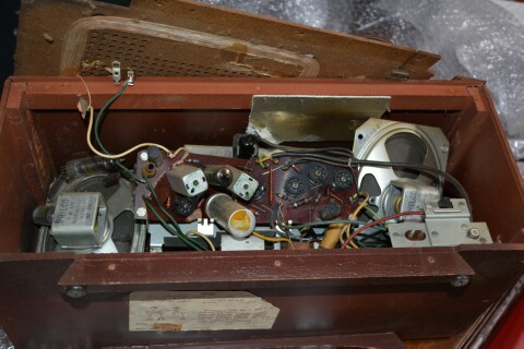
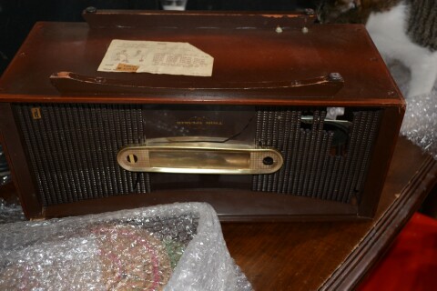
You've possibly seen these lovely pics of the E-818 I got in the other day:


Well.. tonight I started to try to revive it. I super glued the pieces of the board back together (not an easy task on its own, since I had to patiently hold the pieces together till the glue set). Then I began to reinforce the cracks by bridging solder across the crack on each trace. Once that was done, I further reinforced the connections by running small gauge stranded wire all along the traces, attaching them to hard solder points at each end.
I've got filaments now, and 157 VDC at every B+ point, so obviously I've missed a break somewhere (not really surprising, there were a LOT of them!) Once I have found and repaired all broken traces, I plan to coat the entire bottom of the PC board with epoxy to prevent it breaking too easily again.
I've also patched the speakers, and mended the broken terminal strip on the loop antenna.
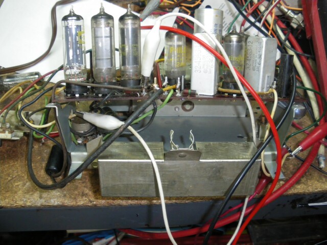
So far, this is what it looks like, at least from the front of the chassis.

So, now, supposing I get this all working properly, I'm not at all sure what I'm going to do with it, since the front panel is pretty well hosed, and I doubt there are enough pieces left to mend it properly. I have, however, repaired the wooden cabinet, and it looks quite presentable.
(This post was last modified: 02-23-2014, 10:34 AM by BrendaAnnD.)
Posts: 1,562
Threads: 56
Joined: Nov 2008
City: Sedona, AZ/Placentia/CA
Nice work Brenda, you truly are a glutton for punishment. I enjoy watching your work.
By the way, what is that "clip" in the last picture for? Looks like something to hold an eye tube.
Jerry
A friend in need is a pest! Bill Slee ca 1970.
Posts: 1,106
Threads: 88
Joined: Jun 2011
City: Tacoma
State, Province, Country: Washington
Holds the socket for the C-7 dial lamp.
Posts: 1,106
Threads: 88
Joined: Jun 2011
City: Tacoma
State, Province, Country: Washington
It sings. Took locating 5 more broken traces, two in the screen supply to the outputs and the screen/plate supplies to the front end tubes. One to the detector. One to one of the plates of the 25F5's (which, I find, are just half voltage versions of 50C5's.) Also had to repair the LO coil, which had been bent out of its plane and the center tap needed to be reconnected to the lug. Now to see what I can do with that poor cabinet front...
Posts: 1,114
Threads: 14
Joined: Feb 2013
City: Irvington, NY
Whats going on with the two output tubes? Does each speaker have its own tube and output transformer, or are they in parallel?
Posts: 16,582
Threads: 574
Joined: Oct 2011
City: Jackson
State, Province, Country: NJ
It is an FR2 PCB right?
Yeah....you are a glutton for punishment borderline masochistic. 
My old experience with Russian TVs - those were the only devices I saw using FR2 PCBs and tubes:
lots of times due to the tubes panels getting hot (yes, with the miniature tubes) the pins of the panels develo cold solder spot around them. When looking at it it might even look normal but touch it with soldering iron and the solder becomes powdery and the pin inside is not wetted and oxidized. And even the solder pad could be grey and not wetted with solder.
Also sometimes due to the weight of the tubes and the temperature the solder pad start separating and eventually tearing off the traces.
Check for that just in case. At least in the TPA-1 all transistor player it did not take any temperature rise, about 1/3 of the solder pads we separated and tore off.
Posts: 1,222
Threads: 86
Joined: Jan 2014
City: Annapolis, IL
State, Province, Country: USA
Brenda, that is amazing! Did someone drop that thing off a cliff or went through a nuclear powered blender? I have repaired several busted up pc boards over the years, including an entire corner broken off a tv around the flyback. One thing I learned, and might mention is future repairs. If that board is completely covered in epoxy underneath, imagine the fun next time you need to repair something, like a hairline crack that got missed. Just ... been there - done that.
If I could find the place called "Somewhere", I could find "Anything" 
Tim
Jesus cried out and said, "Whoever believes in me , believes not in me but in him who sent me" John 12:44
Posts: 1,106
Threads: 88
Joined: Jun 2011
City: Tacoma
State, Province, Country: Washington
Madmurdock,
Understood. I feel it needs SOME sort of reinforcement. Perhaps a couple layers of duct tape applied to the bottom of the board. It seems stable now, and plays pretty well.
Morzh,
First thing I do on PC boards with tubes is to go around every socket and reflow the solder. Learned that one a LONG time ago.
Mondial,
Tubes are in push-pull. another of Philco's oddball drive arrangements. This one's not even the one with the screen feeding the alternate tube, it seems to make use of a negative feedback loop off the transformer secondary.
Posts: 16,582
Threads: 574
Joined: Oct 2011
City: Jackson
State, Province, Country: NJ
Was probably a longer time for me - learned that some time end of 70s.....
Posts: 1,106
Threads: 88
Joined: Jun 2011
City: Tacoma
State, Province, Country: Washington
For me it was sometime in the 70's as well. I'm no spring chicken, you know.  Just a baker's dozen months till I turn 60.
Posts: 1,562
Threads: 56
Joined: Nov 2008
City: Sedona, AZ/Placentia/CA
Aw BAD, I figured in your 40s! Enjoy your help and your a smart spring chicken.
Jerry
A friend in need is a pest! Bill Slee ca 1970.
Posts: 16,582
Threads: 574
Joined: Oct 2011
City: Jackson
State, Province, Country: NJ
Me too! Is this a current photo?
Posts: 1,106
Threads: 88
Joined: Jun 2011
City: Tacoma
State, Province, Country: Washington
I think about 7 years ago. Though I really still look pretty much the same, but with a bit more grey in my hair.
Posts: 16,582
Threads: 574
Joined: Oct 2011
City: Jackson
State, Province, Country: NJ
Posts: 1,106
Threads: 88
Joined: Jun 2011
City: Tacoma
State, Province, Country: Washington
Thanks.  Always makes me feel good when someone figures me for 40-ish. (which happens a lot more often that you think.)
Users browsing this thread:
|
|
Recent Posts
|
|
Philco Model 38-7: what caps & resistors do fail typically?
|
| Since you stated earlier, you have a console 38-7XX. They also had a 38-7T (table), and 38-7CS (chairside). A very nic...GarySP — 01:18 PM |
|
Part numbers to model cross
|
| That I wouldn't know, but sometimes the radio document itself shows one, same as the capacitor cans' etc pinouts.morzh — 12:46 PM |
|
Part numbers to model cross
|
| Thank you morzh, that is exactly what I was looking for. Now , is there some where that shows pinouts for Philco power ...Jim Dutridge — 11:37 AM |
|
Restoration of the Canadian General Electric A-87
|
| Thanks for your help Michael. In fact, this video is only an intermediate result. Later I had to apply another tinting l...RadioSvit — 09:01 AM |
|
Restoration of the Canadian General Electric A-87
|
| Great job on the cabinet.
PS. In the US notation, "kenotron" refers to specific type of tubes; we call re...morzh — 08:24 AM |
|
Part numbers to model cross
|
|
This document has at least some tables of models and parts used.
Example: Choke 32-7572, used in 604 radio.
Search f...morzh — 08:19 AM |
|
Restoration of the Canadian General Electric A-87
|
| I also checked all the radio tubes on my Hickok 530 tube tester. The 5Z3 kenotron turned out to be faulty, all the other...RadioSvit — 08:02 AM |
|
Restoration of the Canadian General Electric A-87
|
|
Well... While the varnish is drying up, I started repairing the chassis...
Of course I started by replacing the pa...RadioSvit — 07:12 AM |
|
Philco Model 38-7: what caps & resistors do fail typically?
|
| Hello Martin,
Welcome aboard our little community what great Model 38-7
Sincerely Richardradiorich — 12:30 AM |
|
Philco Model 38-7: what caps & resistors do fail typically?
|
| Welcome to the Phorum Martin.
I count about 9 paper caps, the 3 electrolytic caps and 2-Y2 safety caps to replace th...RodB — 09:44 PM |
|
Who's Online
|
There are currently 1239 online users. [Complete List]
» 2 Member(s) | 1237 Guest(s)
|
|
|

|
 
|


![[-] [-]](https://philcoradio.com/phorum/images/bootbb/collapse.png)


