Posts: 285
Threads: 18
Joined: Nov 2016
City: Cromwell
State, Province, Country: CT
I have always wanted a really high end console radio that I could actually afford. The 1000Z, Baby Strats, Scott sets were pretty much out of my range. I got lucky back in October 2017 and I purchased a 38-690 locally here in CT from an ARF Member. It was only a 2 hour round trip and my brother in-law helped me get it home. The radio was sold in operating condition, but there were issues. Knowing that I was planning on a full restoration, I would tackle each item one at a time.
I did a post in the refinishing thread when I was working on the cabinet, but I figured I'd show the complete radio project from start to finish.
Here is a list of what needed to be done.
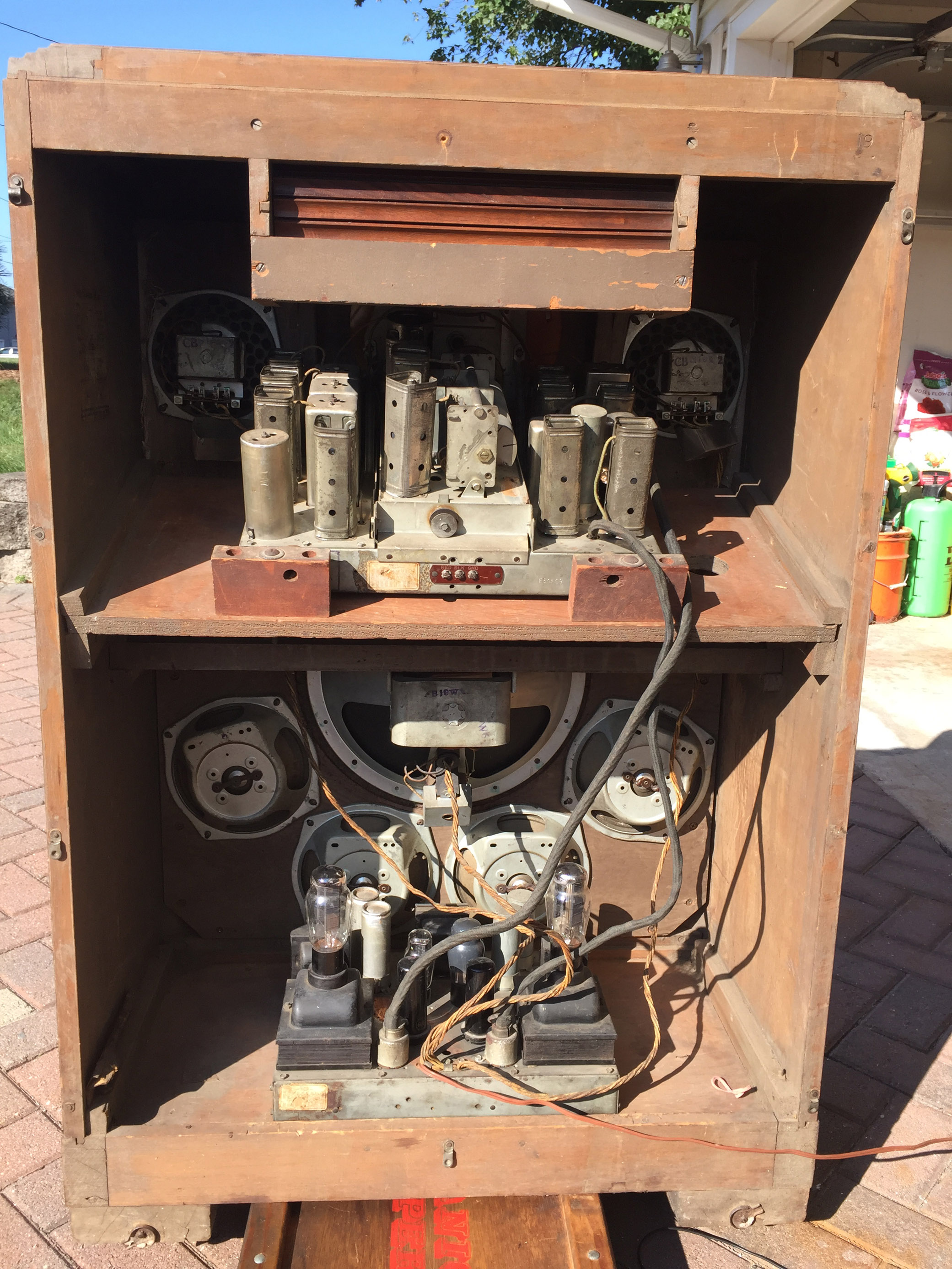
Repair the previous electronic restoration. Many bad solder connections were found, and caps were missed. Also many out of tolerance resistors, and 2 candohms that will be replaced. Note: There were no paper caps left for me to restuff, so I left it alone and stuck with modern caps.
Stuff the electrolytic cans with 630 V film caps.
Rebuild the RF sub chassis. only two caps were replaced and all the rest were original.
Paint the rusty main chassis, sub chassis, and power/amp chassis.
Repair the cracked dial. It was spinning loosely.
Repair the audio muting switch.
Perform an Alignment.
Refinish the cabinet. A poor attempt at refinishing before left me with a layer of polyurethane to remove.
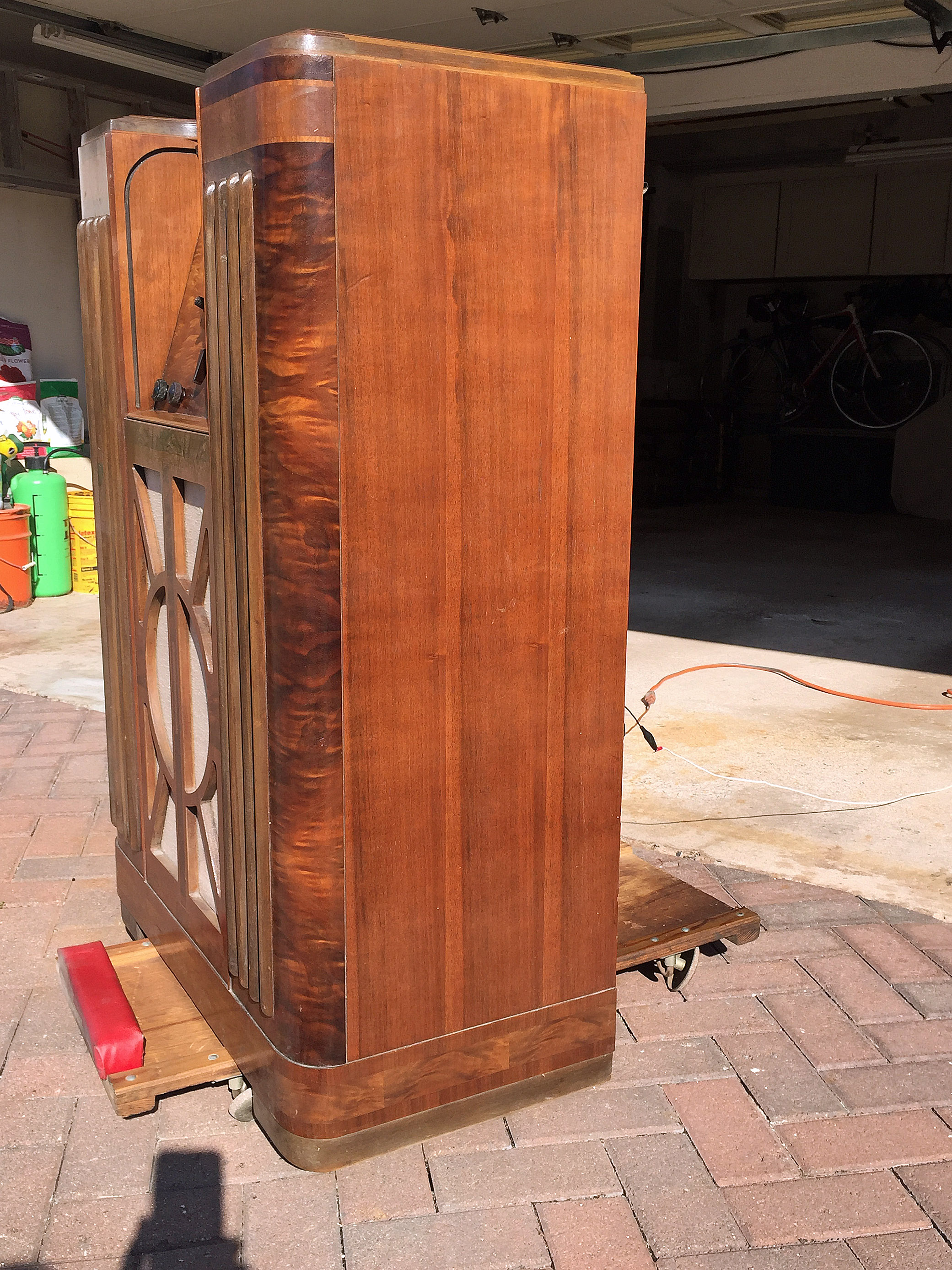
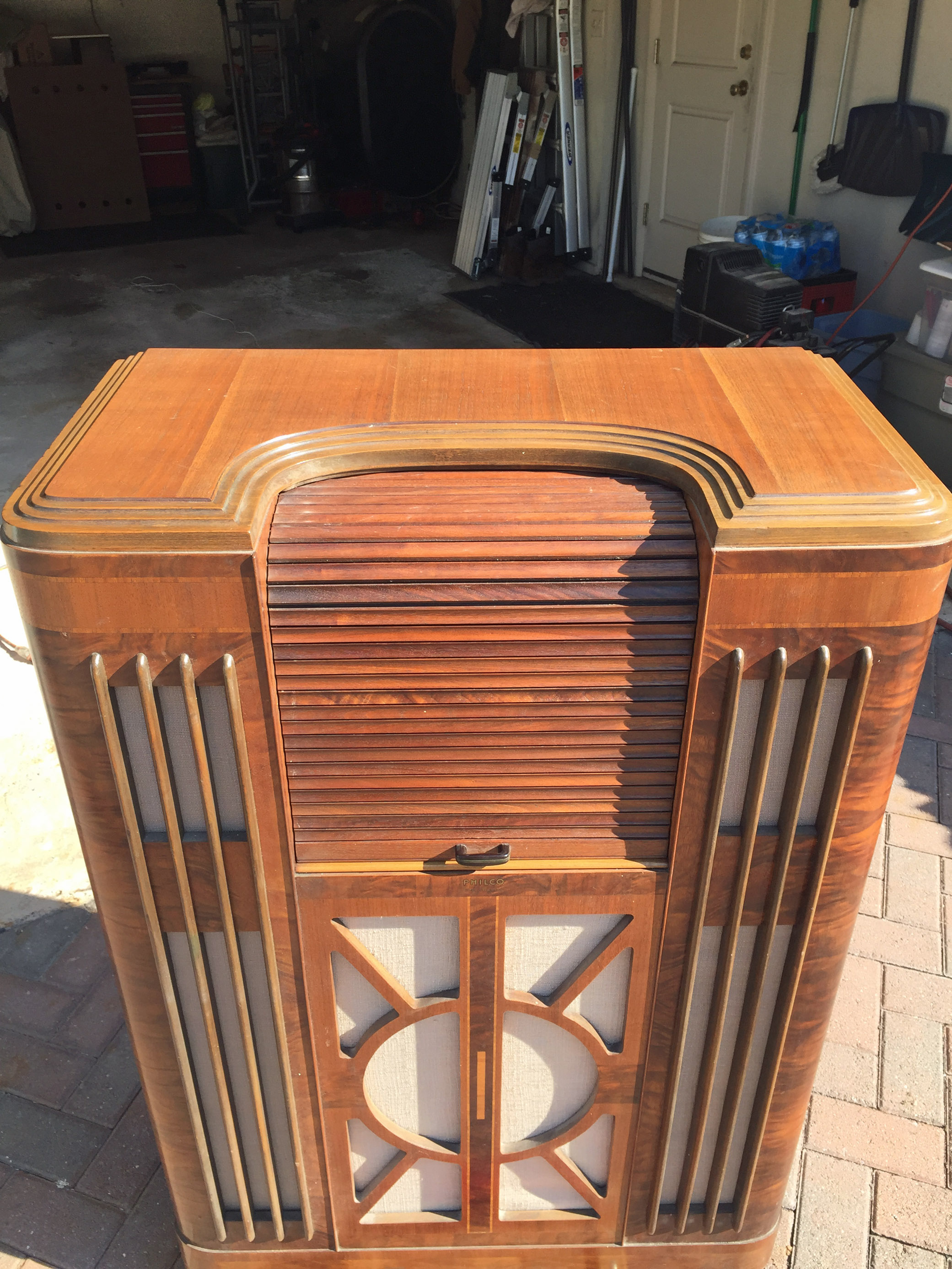
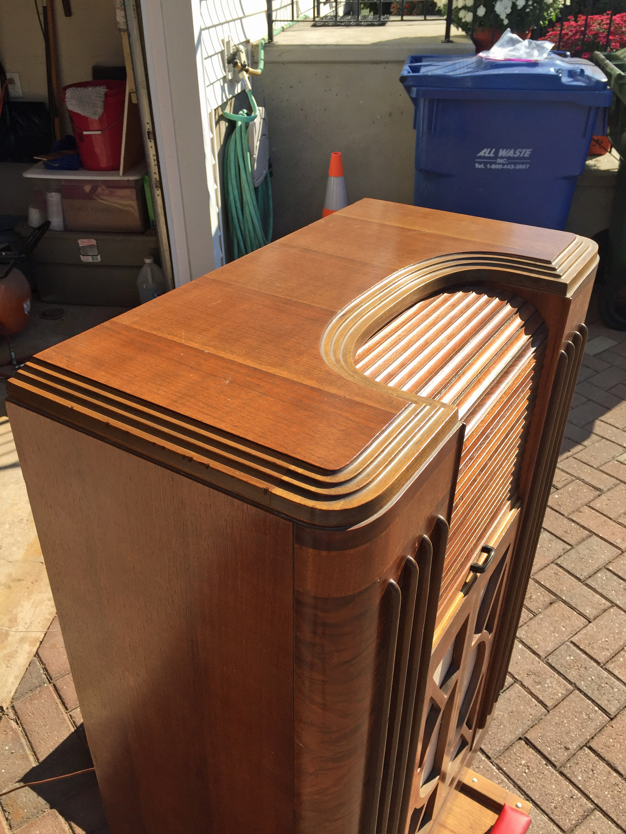
Here are the before pictures. More to follow.


Tony
“People may not remember how fast you did a job, but they will remember how well you did it”
Posts: 285
Threads: 18
Joined: Nov 2016
City: Cromwell
State, Province, Country: CT
Posts: 16,579
Threads: 574
Joined: Oct 2011
City: Jackson
State, Province, Country: NJ
Before pics are not bad at all. This radio is in good shape.
People who do not drink, do not smoke, do not eat red meat will one day feel really stupid lying there and dying from nothing.
Posts: 2
Threads: 1
Joined: Jul 2018
City: Brooklyn
State, Province, Country: New york
I have this same model. Mine is just slightly different. Mine has a round knob in the center of console & i also have a brass tag on the front. It says exact replica of the ten millionth philco built for walton jones.
Cant find any info on the tag. Yours looks great.
Posts: 285
Threads: 18
Joined: Nov 2016
City: Cromwell
State, Province, Country: CT
Posts: 285
Threads: 18
Joined: Nov 2016
City: Cromwell
State, Province, Country: CT
Posts: 285
Threads: 18
Joined: Nov 2016
City: Cromwell
State, Province, Country: CT
Mike,
The original pictures don’t show the runs on the front panel well. But that was the point where I decided to just refinish it.
Tony
“People may not remember how fast you did a job, but they will remember how well you did it”
Posts: 246
Threads: 27
Joined: Aug 2013
City: Petaluma, CA
Absolutely beautiful work, Tony! All aspects of your restoration are top notch. A radio such as that deserves nothing but the best and that's what it received! Even my wife would allow that beautiful console in the house!
Craig R
Posts: 94
Threads: 9
Joined: Feb 2013
City: Monroeville, PA
Great job! The radio looks really good. How did you paint the chassis? Did you remove everything and spray it or did you use a brush to get around things.
Posts: 120
Threads: 15
Joined: Aug 2017
City: Fort Worth
State, Province, Country: TX
Wow! Your time was well spent on creating a masterpiece!
Posts: 285
Threads: 18
Joined: Nov 2016
City: Cromwell
State, Province, Country: CT
Hi Bill
I used Rustoleum Satin Nickle Metalic spray paint.
https://spraypaint.rustoleum.com/product...ray-paint/
I took of the major components off the radio and sub chassis. The IF transformers and all coils had the covers removed and then they were masked off. I took the time to block off any openings that the paint could get into. Metallic paint under a chassis near wiring could have a bad outcome.
I put wide masking tape over the tube sockets and cut off the excess with an exacto knife leaving a small disk over just the socket. Also, the piece that the tube shields go over was cleaned and masked off.
On the amp chassis, I removed the caps and filter chokes as the needed painting.
I masked around the power transformers and painted them on the chassis. Then they were masked off and the chassis was painted.
The tube shields were painted with a chrome paint. Maybe not as shiny as original, but better than they were.
Took some time, but the outcome was worth it. I couldn’t leave the rust showing when the cabinet was going to look nice.
Tony
“People may not remember how fast you did a job, but they will remember how well you did it”
Posts: 32
Threads: 1
Joined: Jun 2018
City: Mount Jackson
State, Province, Country: VA
Users browsing this thread: 1 Guest(s)
|
|
Recent Posts
|
|
Philco Model 38-7: what caps & resistors do fail typically?
|
| Hello Martin,
Welcome aboard our little community what great Model 38-7
Sincerely Richardradiorich — 12:30 AM |
|
Philco Model 38-7: what caps & resistors do fail typically?
|
| Welcome to the Phorum Martin.
I count about 9 paper caps, the 3 electrolytic caps and 2-Y2 safety caps to replace th...RodB — 09:44 PM |
|
Part numbers to model cross
|
| Jim,
We have this index put together by Dale Cook but I don't think that is quite what you are looking for.
The Parts...klondike98 — 09:37 PM |
|
Philco Model 38-7: what caps & resistors do fail typically?
|
| Yep the dim bulb test is OK but I'd definitely replace all those electrolytics before I did it. Since those #47 conden...klondike98 — 09:18 PM |
|
Philco 42-345 Restoration/Repair
|
| The resistor is a 2.2 Meg, it was the last one I hadn't replaced. The broadcast is coming in after replacing it.osanders0311 — 09:09 PM |
|
Philco 42-345 Restoration/Repair
|
| What does the resistor measure? I think it should be 3.3 Meg.
If the oscillator coil has continuity and the resistanc...RodB — 09:03 PM |
|
Philco Model 38-7: what caps & resistors do fail typically?
|
| Good idea to check the coils... then I'll get hold of an incadescent light bulb and see what happens when the unit is sw...Musaeum — 08:49 PM |
|
Philco 42-345 Restoration/Repair
|
| I have that same set, ain't too much shortwave I like anyway.....it is a good AM DX set. PaulPaul Philco322 — 08:32 PM |
|
Philco Model 38-7: what caps & resistors do fail typically?
|
| Welcome to the Phorum, Martin! Open a new thread in Philco Electronic Restoration when you begin working on your 38-7. ...GarySP — 08:28 PM |
|
Philco Model 38-7: what caps & resistors do fail typically?
|
| Welcome to the Phorum!
:wave:
Here's the schematic for that radio from our digital library:
Something to do bef...klondike98 — 08:05 PM |
|
Who's Online
|
| There are currently no members online. |

|
 
|


![[-] [-]](https://philcoradio.com/phorum/images/bootbb/collapse.png)


