Welcome Guest! Be sure you know and follow the Phorum Rules before posting. Thank you and Enjoy! (January 12, 2025) x

Thread Closed

Philco 41-226 electrolytic voltages
#1

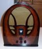
Picked up a 41-226 sled. This uses a dual 20mfd cap part number 30-2491

After looking through the catalogs I see no
listings for this part. The schematic lists the voltages as 90 and 120 across the caps

I assume that a 150v cap is sufficient as a replacement???
Looking forward to rubber wiring (not), but it seems basically sound. I’ll be needing to sand out this scratch, looks ok otherwise


Attached Files Image(s)
           
#2

After switching on, the voltage can reach 120 V * 1.414 = 170 V.
Later, after all the tubes have heated up, the voltage will reach the nominal value.
The minimum voltage for these capacitors is 200 V. Better is 250–300 V.

If you want to work, lie down and sleep, and everything will pass.
#3

Electrolytic capacitors were rated in "working volts" (WV) and could take a certain amount of overvoltage.  In theory, the voltage could be more than 150, but in practice, there is a rather high voltage drop across a 35W4, 35Z5 or similar tube.  These tubes took a longer time than a 5Y3 or similar tube to heat up to full output.  I would stick with 150WV or 160WV.  I wouldn't go above 200WV

When I was young, the practice was to not use an electrolytic capacitor with a much higher working voltage value because the cap would not "form" or have the same capacity at a lower voltage than rated for.  This was a property of electrolytic capacitors, not of the paper-foil capacitors which should be replaced with caps having the highest practical voltage value.

"Do Justly, love Mercy and walk humbly with your God"- Micah 6:8
"Let us begin to do good"- St. Francis

Best Regards, 

MrFixr55
#4

Ok. Thanks. I went with the 160WV as suggested. They’re cheaper and the values matched exactly. Not that 22mf vs 20 mf means much.
#5

Those old 20s had a tolerance of 20 percent, as most of the components in these old sets.



Users browsing this thread: 1 Guest(s)
[-]
Recent Posts
under chassis parts locator diagram for 1938 Zenith 9s262
Has anyone gone to the trouble of creating an under chassis parts locator image?  Yes, I can identify components by foll...bobloney — 08:57 PM
Plug Voltages Needed For A 1943 CRV-20130 Power Supply
Try looking at this site the book mark is for a old generator that I was given. David    https://radionerds.com/index.ph...David — 08:36 PM
Plug Voltages Needed For A 1943 CRV-20130 Power Supply
Hello Everyone, I am looking for voltage identification for all the pin positions on the socket of a CRV-20130 power su...Tonym4704 — 08:16 PM
Philco P45-6365 Universal Transformer Instruction Manual
Can anyone guide me to where this may be found?GRG — 03:00 PM
54C Complete Teardown/Rebuild
I don't think that I have encountered a 12Z3 before, curious how it uses one of those but includes a #43, which is a 25 ...Arran — 02:17 PM
HiFi (Chifi) tube amp build - but my own design.
It's the other forum. I'm also in DIY, but mostly read there. Honestly, I kinda jumped into this without much thought to...TV MAN — 10:43 AM
Philco 71 Code 125
Hello,  I am in need of a schematic for this radio. Mine has the three separate circular tube shields and a shadow me...dconant — 08:06 AM
Stromberg Carlson 1500 Squeal
And life just keeps getting more complicated.dconant — 07:57 AM
54C Complete Teardown/Rebuild
Hello Roy, here is this one sincerely Richardradiorich — 12:45 AM
54C Complete Teardown/Rebuild
Richard, Had grabbed it already but thank you just the same.  I find myself wanting to find some way to block out the...glyphmon — 12:03 AM

[-]
Who's Online
There are currently 1945 online users. [Complete List]
» 1 Member(s) | 1944 Guest(s)
Avatar

>