Re-stuffing metal bodied capacitors.
Posts: 816
Threads: 25
Joined: Mar 2014
City: Louisville, KY

Ok . . . so what's the next step?
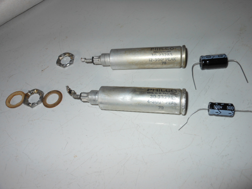
The 12 mfd. wasn't too much problem to remove, but it took an act of god to get the 4 mfd. out of the chassis . . . you can see the marks and dents I left on the can. <sob>  When I couldn't get the nut below the chassis to turn WITHOUT a tool holding the top, I started grabbing the tip top of the thing with a 2nd set of pliers to get that chintzy nut to turn. Usually, that type of nut is FALLING off after looking at them the wrong way !
With the grabbing of the can with a pliers, that top end didn't loosen like I thought it might have, . . . so if I have to take that end cap off, it ain't gonna come easily either. 
Posts: 1,475
Threads: 69
Joined: Nov 2012
City: Kansas city, MO.
Hi Jake your going to have to cut that can open. I would use a box cutter or hacksaw and cut it along the groove at the top. That way you can glue the top back on. Now fun starts, getting the guts out of the can.
I usually use a large lag type bolt and screw it into the can and heat the can up a bit with a bernzomatic torch and pull the innards out.
There are other ways to do this. It's what works best for me. PS if you have a vice put the bolt in the vice and then screw the can onto the bolt it will give you better leverage to pull the can just have to use a rag to hold it after heating it up.
(This post was last modified: 03-21-2019, 03:09 PM by KCMike.)
Posts: 15,743
Threads: 551
Joined: Oct 2011
City: Jackson, NJ
There are two schools of cutting the cap:
1) cut close to the bottom, so that the cut line is somewhere withing the clamp holder. Then a plastic tube (plumbing pipe of the right gauge) is glued inside and the two halves are aligned and glued.
Advantages: easily restuffed as the access to the bottom where the new caps are located is unrestricted.
Disadvantages: 1) The plastic tube take space and gives less space to the new caps, 2) Good only for the clamp mount.
2) Cut the cap off. Then upon cleaning, restuff and re-glue the cap back on.
Advantages: looks good without clamp (good for both clamp and nut mounts).
Disadvantages: tall cylinder makes it more difficult to work on the bottom.
People who do not drink, do not smoke, do not eat red meat will one day feel really stupid lying there and dying from nothing.
Posts: 691
Threads: 8
Joined: Apr 2018
City: S. Dartmouth
State, Province, Country: MA
https://www.homedepot.com/b/Tools-Hand-T...5yc1vZc6f0.
Maybe too large but the concept can be used with small nylon webbing and vice-grips...
I have only stuffed the copper ones some 40ya. I have not done more. I use added terminal strips below chassis, leave the OEM caps fully disconnected...
IMHO stuffing is overrated, I have done well with tie strips and radial caps strategically placed. Never had an oscillation problem. None the less the Bakelite blocks have to be stuffed but that is an easy task...
YMMV
Chas
Pliny the younger
“nihil novum nihil varium nihil quod non semel spectasse sufficiat”
Posts: 1,188
Threads: 49
Joined: Oct 2017
City: Allendale, MI
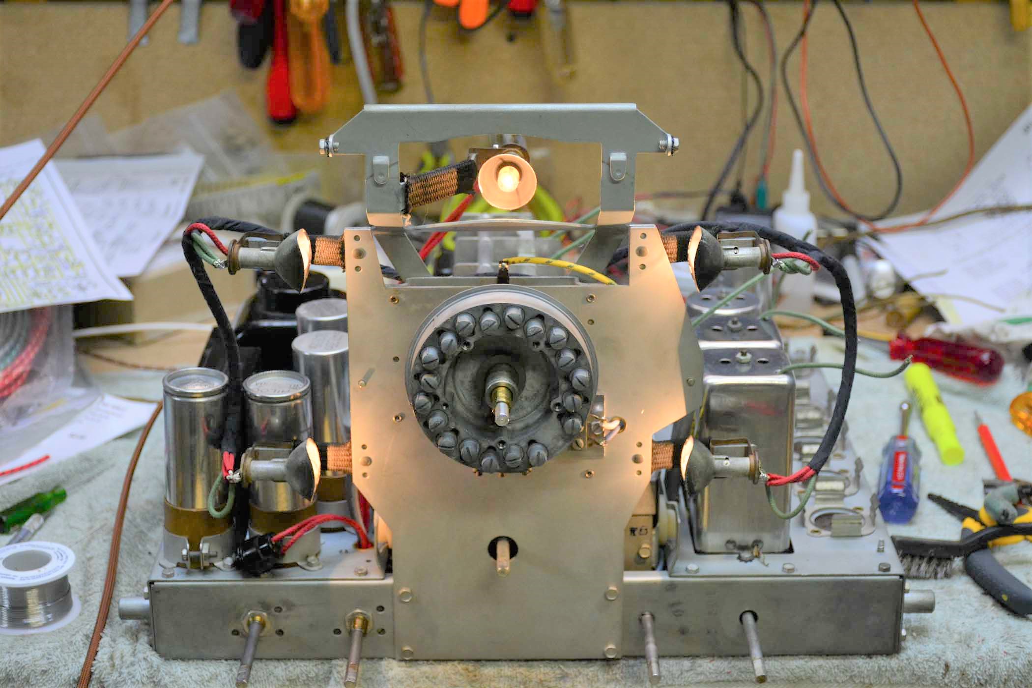
Here's a photo of 4 cans. The front 2 were cut at the top and glued together again - method 2. The back 2 didn't have the top crimp so they were cut and glued together again under the clamp and cardboard insulator - method 1. Both look very original and the underside of the chassis also looks original, if that is important to you.

Posts: 816
Threads: 25
Joined: Mar 2014
City: Louisville, KY
KCMike
I do have a vice, so I'll remember that when I go to screwing the lag. Wondering if a heat gun is adequate....have one of them also. Thanks for the tip bud.
Jake
Posts: 816
Threads: 25
Joined: Mar 2014
City: Louisville, KY
morzh
This model uses no clamps to hold those filter caps in. So that means option # 2. Thanks.
Jake.
Posts: 816
Threads: 25
Joined: Mar 2014
City: Louisville, KY
Chas,
There is definitely something to be said for leaving the cans in physically, and clipping wires and installing under the chassis, as opposed to the extra work with stuffing....done that under-the-chassis-thing numerous times already, with good success. I became curious about the stuffing idea after I viewed a few videos of some other restorers stuffing for originality's sake. They even stuff cardboard ones, but I think that goes a bit far, . . . . I would rather get rid of that much more flammable material from these heat-producing appliances ! Decided to give it a try on this one's metal cans . . . . and maybe on the 89-B when the time comes, if this time works out. Thanks for sharing your ideas.

Jake
(This post was last modified: 03-21-2019, 09:07 PM by Jake Blake.)
Posts: 816
Threads: 25
Joined: Mar 2014
City: Louisville, KY
rfeenstra
They look GORGEOUS! What is that model?
You are obviously a master at this.
I just wish I could have gotten the nut to unscrew without the aid of a Channel-Lock around the one can!
I'll gonna give it a try. The nut-and-bolt style of mounting that mine have, ( no clamp), I think, calls for cutting the top. Thanks for the illustration! I'll keep you posted .
Jake. 
Posts: 1,188
Threads: 49
Joined: Oct 2017
City: Allendale, MI
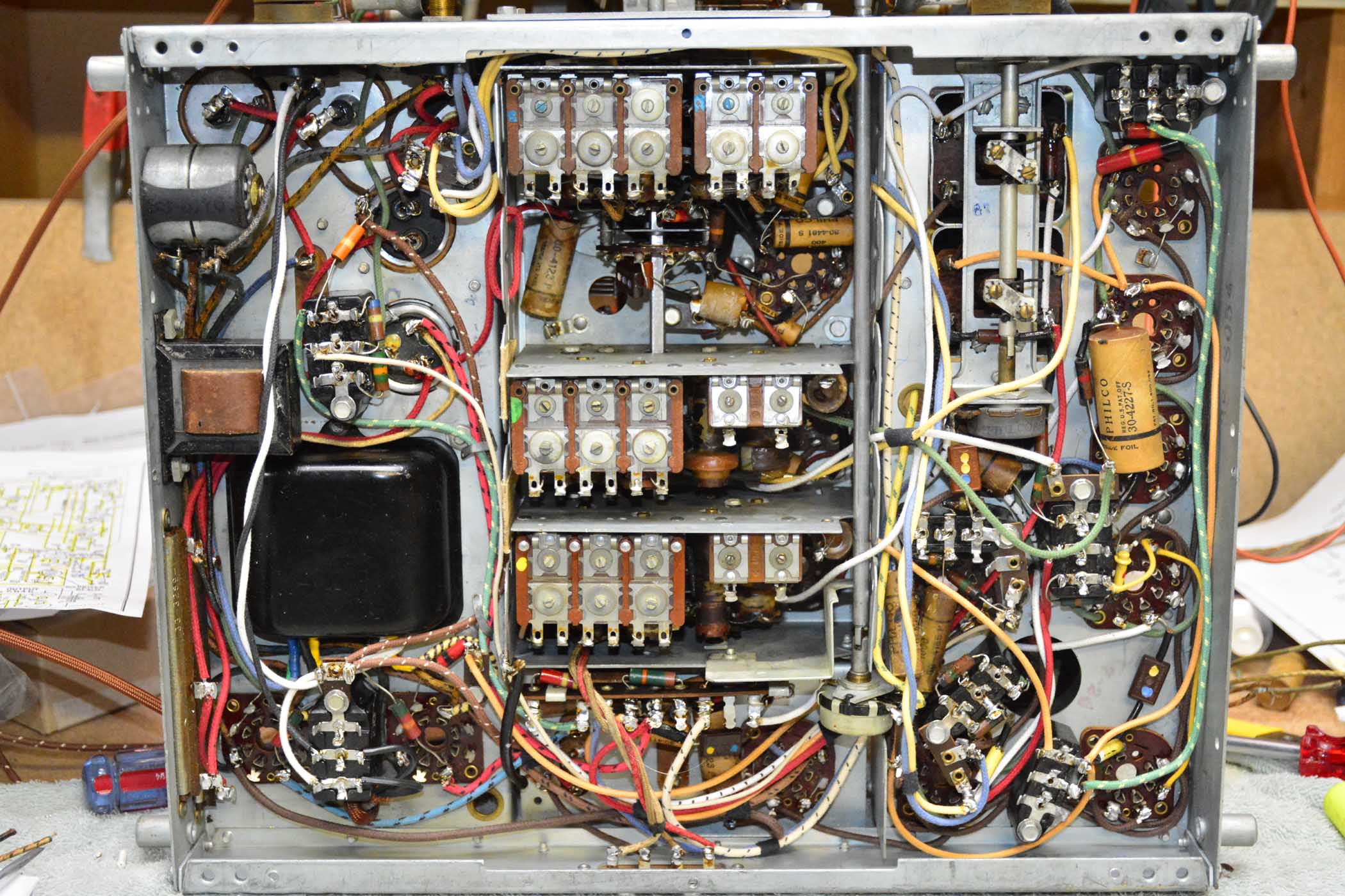
That's the 37-116 I recently finished. Works great. Everything I know I learned on this phorum, and trust me, I'm still learning from the experts here!! The tubular caps are not hard to stuff with new film caps and I really don't like the looks of those bright yellow caps on the bottom side. So, I stuff those as well. A little more work, but for me, more satisfying. Here's the underside. I like it better without all the yellow caps. Just me, and a few others...

Posts: 816
Threads: 25
Joined: Mar 2014
City: Louisville, KY
rfeenstra,
You have your preference bud. Stick with it. That is beautiful!!!
Jake. 
Posts: 4,690
Threads: 51
Joined: Sep 2008
City: Sandwick, BC, CA
If the condenser cans have a rolled over top the chances are good that they are wet electrolytics, the only thing that will have to be removed is the rod with the anode plates attached to it which should pull out through the bottom once the mounting lug is removed.
Regards
Arran
Posts: 691
Threads: 8
Joined: Apr 2018
City: S. Dartmouth
State, Province, Country: MA
I had bought a Hammerlund SP-110-X in '68, in very well used condition. At the time it was not the the project then to restore old commercial/military receivers. The term "Boatanchor" had not yet been coined. The separate power supply had a bank of four stud mounted Aerovox electrolytic capacitors as filters. All leaking electrically very badly to the point of getting hot...
Aerovox had a manufacturing facility on Belleville Ave., New Bedford and a local distributor just some 3 miles away. This type of capacitor was known as the "GL", stud mounted with exiting lead wires. It had long gone out of production, however, a phone call from the distributor discovered they could be made for a very reasonable "special" order. So, I did. It has been some 15 years since I powered that old Hammalund. It did work just fine then in 2005.
I doubt Aerovox would build the "GL", the Belleville plant was torn down and excavated as a hazardous waste site, brown field. In fact I was next door to the "field" on this past Wednesday for a meeting. The nearby Acushnet River was being dredged that day by the EPA for hazardous waste 
Hayseed Hamfest does make twist-loc electrolytics. Reading of the episodes of restorers dealing with the Zenith Transoceanic 4-section twist-lok is like reading events in a torture chamber... There is virtually no room to mount external caps so the OEM unit gets the 'Iron Maiden" treatment. Hayseed has made that go away for the same cost as a steak dinner, some $35...
YMMV
Chas
Pliny the younger
“nihil novum nihil varium nihil quod non semel spectasse sufficiat”
Posts: 2,118
Threads: 112
Joined: Jun 2010
City: Medford OR (OR what?)
Pictures of a copper can cap about 1/2 way down.
Similar cut at the crimp on a aluminum electrolytic only it is not rejoined with solder, rather glue, or if you are really good at it, a press fit (one part slides into the other)
. https://www.russoldradios.com/blog/1000z...raudio-amp
"I just might turn into smoke, but I feel fine"
http://www.russoldradios.com/
Posts: 691
Threads: 8
Joined: Apr 2018
City: S. Dartmouth
State, Province, Country: MA
Ya, when I refurbished a Philco 70, 40ya, I was able to knock the perforated top cab off the condensers. FWIR a Mershon wet electrolytic. I cut the body under the cap, such that the replacement of the cap covered the sins..
China yellow caps did not exist at the time. I used foil/plastic Sprague dipped caps inside the blocks. They were the most reliable at the time, I had used same type to make audio tuning circuits for a RTTY de-modulator.
I had no other motivation to stuff the filter caps other than leaving ugly holes and difficulty locating suitable terminals under the chassis.
Oh, I used Sprague electrolytics inside the cans, they looked so lost inside...
I still play the radio now and then...
Chas
Pliny the younger
“nihil novum nihil varium nihil quod non semel spectasse sufficiat”
Users browsing this thread: 1 Guest(s)
|
|
Recent Posts
|
|
RCA WV-98c
|
| If this is R22, check the voltage on the wiper (86V).
If this is R33, see if the lower pin indeed connected to GND, the ...morzh — 02:29 PM |
|
Philco 38-2 Low Volume
|
| Both sch, the one you showed in the beginning and the one I see on Nostalgia, show 40K for the 2nd audio plate.morzh — 02:25 PM |
|
Model 96 cabinet veneer
|
| I can't figure out what the first step is, let alone the final step. I have tried copying pictures from my hard drive a...TGLager — 01:40 PM |
|
Philco 38-2 Low Volume
|
| I managed to get some more time on this.
Hi Mr. FixIT,
The radio has been recapped. Many of the resistors were rep...dconant — 01:39 PM |
|
Philco 38-2 Low Volume
|
| Thanks guys for the help. I started looking at these points but I have to quit for the day. I will be looking into this ...dconant — 12:23 PM |
|
RCA WV-98c
|
| Check out this crazy zero pot operation. Touching it drives it crazy. Its rubber tipped. Also the 6al5 has no negative v...daveone23 — 12:08 PM |
|
Philco 38-2 Low Volume
|
| If you check all of that and still have a problem (my first inkling would be one of the 6F6s) then look at the 6J5 phase...RodB — 10:44 AM |
|
RCA WV-98c
|
| Those will probably depend on teh switch combination.
Could you list some that you see, their values and what they sh...morzh — 10:26 AM |
|
Model 96 cabinet veneer
|
| You are probably skipping the final step. Once you select the photos you want and they get downloaded, the system assign...RodB — 09:36 AM |
|
RCA WV-98c
|
| At this point, there is no input, just internal voltages
Which are incorrect and not sure what they should be.daveone23 — 09:15 AM |
|
Who's Online
|
There are currently 1219 online users. [Complete List]
» 3 Member(s) | 1216 Guest(s)
|
|
|

|
 
|


![[-] [-]](https://philcoradio.com/phorum/images/bootbb/collapse.png)


