Posts: 10
Threads: 5
Joined: Oct 2020
City: Beverly Hills
State, Province, Country: Michigan
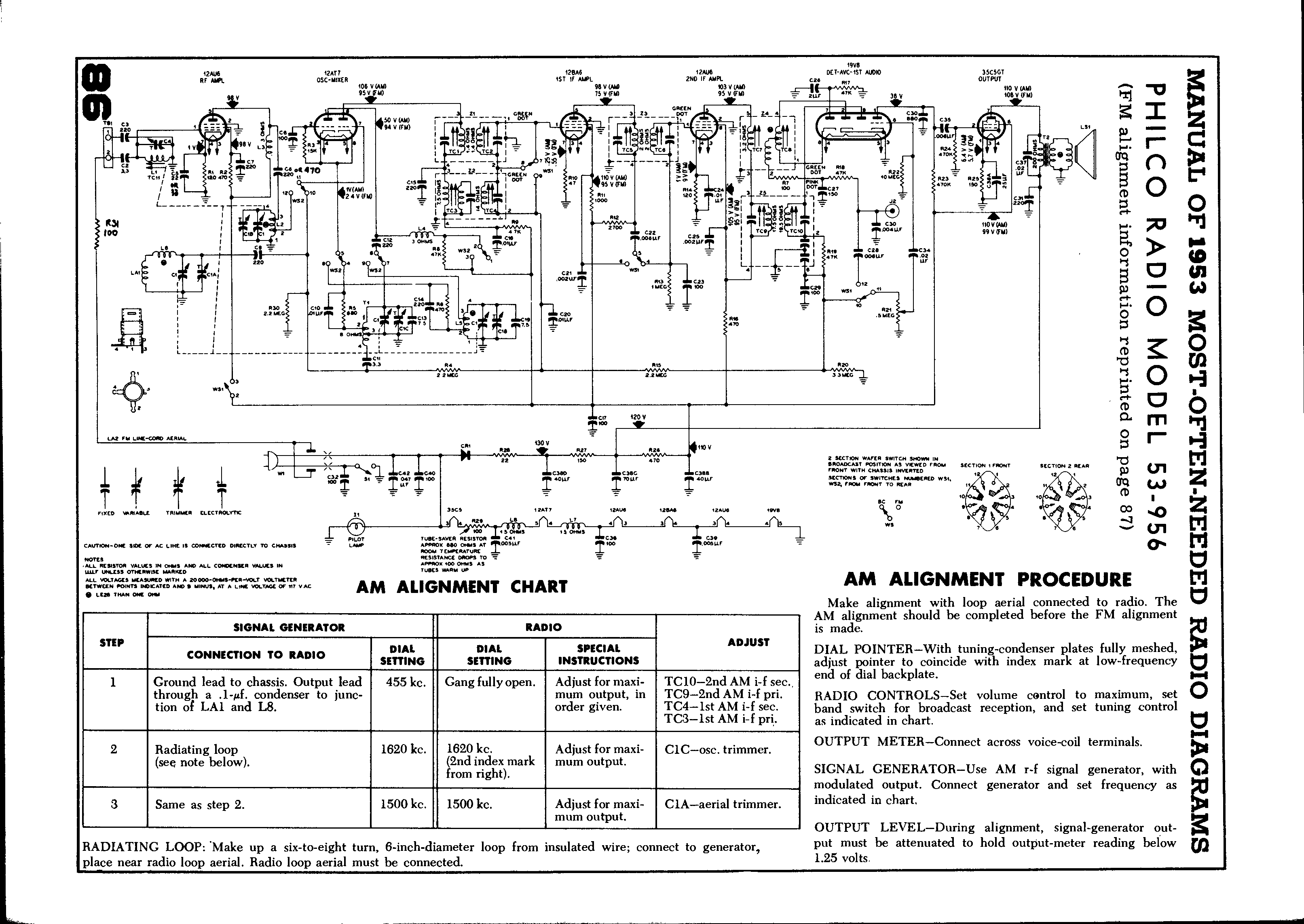
Looking for a little help on this radio. i am somewhat of a beginner on understanding schematics. For this radio the Base View Part Placement
diagram shows no connection on 38A & 38B, but the Philco schematic shows different. The way I see the schematic is:
38A go to Pin 2 of the Output tube
38B go to Pin 1 of the 1st Audio tube
38C go to Pin 7 of the Output tube
38D go to Pin 1 of the Output tube
C26 go to Pin 7 of the Output tube
I got all my info from Nucow Schematics Vol 23, pages 661-666
Any and all help would be much appreciated.
Once again Thanks,
Rick Clark
Posts: 1,183
Threads: 23
Joined: Jan 2014
City: Wellborn Florida

Some info from beitmans need to go look at my note books have worked on the same set a number of years ago. David
Posts: 1,183
Threads: 23
Joined: Jan 2014
City: Wellborn Florida
Back again Nostalgia air is your friend, page 7 was lots of help to me.
http://www.nostalgiaair.org/Resources/785/M0013785.htm
Posts: 7,283
Threads: 268
Joined: Dec 2009
City: Roslyn Pa
Hi Rick
Methinks I see the problem. Your using the parts layout diagram to check the wiring on the diagram. Doesn't work that way. The layout doesn't have all of the connection that are on the diagram. Gonna have read the diagram to see what's what.
Typically all of the schematic for a given set are the same because they come from the manufacture. They're copied by Riders, Beitman or an other outfit. The exception is Sam's they would redraw and renumber everything. For the most part they are neater than the originals and list universal replacement parts. Does make it difficult to follow if your trying to follow a long using two different schematic. Sam's start at 1946 so nothing before that.
When my pals were reading comic books
I was down in the basement in my dad's
workshop. Perusing his Sam's Photofoacts
Vol 1-50 admiring the old set and trying to
figure out what all those squiggly meant.
Circa 1966
Now I think I've got!
Terry
Posts: 10
Threads: 5
Joined: Oct 2020
City: Beverly Hills
State, Province, Country: Michigan
Thanks David, I have the same information. What I was looking for, was for someone to verify
my understanding of the schematic tracing the wiring back to the tubes.
Once again
Thanks,
Rick
Posts: 1,183
Threads: 23
Joined: Jan 2014
City: Wellborn Florida
Looking at my notes 11 pages 38A used a 22UF at 50 volt 38BCD 47UF each at 220 volt, items I try to have on hand. Replaced CR with 2-1N4007, R28 increased to 50 ohms. The reason for the change in R28 the CR would drop voltage by 7 volts the 1N4007 only drops voltage 7/10 of a volts. My 12AT7 tube only worked on AM but not FM. The 19V8 tube worked Ok replaced with a NOS what a difference, other tubes ok. This was a project from May-July of 2011. Nothing in my notes on problems with installing the replacements for 38ABCD. Stay Safe David
Posts: 1,824
Threads: 114
Joined: Jul 2014
City: Sneedville, TN
Not sure about the fitment on your set, but I found this,
https://www.tubesandmore.com/products/ca...50505050-f I know it's a bit pricey, but the multi section cans are more difficult to stuff than the older single section ones. If it would fit, this would work.
(This post was last modified: 03-27-2021, 09:18 PM by
mikethedruid.)


![[-] [-]](https://philcoradio.com/phorum/images/bootbb/collapse.png)


