Posts: 15
Threads: 2
Joined: May 2013
City: United States
I recently purchased a Philco Model 20 from a local Salvation Army store.
I powered it up with a dim bulb and variac to be safe. It has audio with no hum associated with bad filter caps and it doesn't smoke (a good thing)
but it's not picking up any stations. Not bad for something 83 years old.
It has a wire for an antenna.
Pete
Posts: 2,128
Threads: 18
Joined: Oct 2008
City: Merrick, Long Island, NY
Schematic and other info here: http://www.nostalgiaair.org/PagesByModel...029582.pdf
It is recommended that you change out all the electrolytic and paper capacitors, and it is easy and cheap enough to replace the carbon resistors (many of which will have drifted way up or become otherwise tempermental) at the same time before powering the set up again. Any rotted out or ratty wires including the line cord should also be replaced as well.
Then let's see what you have.
Posts: 1,957
Threads: 146
Joined: Jan 2013
City: Westland, MI
Would also recommend installing a fuse inline before the switch. Better to see a two dollar fuse turn to toast than a power transformer. Take care. Gary
"Don't pity the dead, pity the living, above all, those living without love."
Professor Albus Dumbledore
Gary - Westland Michigan
Posts: 4,682
Threads: 51
Joined: Sep 2008
City: Sandwick, BC, CA
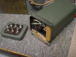
The Philco 20 has large paper capacitors for filters, likely contained inside a tar filled can somewhere on the chassis along with several bypass capacitors. These capacitors last longer then electrolytics and tubular paper caps but the set is over 80 years old now so one or more of these may have failed causing no reception. Also sometimes the Model 20s can have one or more of the RF coils fail causing a dead radio, they can be checked for continuity with an Ohm meter. Like many radios of this era another common failure is the audio interstage transformer going open on the primary side.
Regards
Arran
Posts: 1,957
Threads: 146
Joined: Jan 2013
City: Westland, MI
By the way...welcome to the phorum. I'm re-building a Model 20 also, but not in any hurry. Tons of posts here to help you rebuild the components, and very friendly members to help when you get stuck. Take care. Gary
"Don't pity the dead, pity the living, above all, those living without love."
Professor Albus Dumbledore
Gary - Westland Michigan
Posts: 270
Threads: 12
Joined: Nov 2005
City: Nashville, TN
Hi Pete,
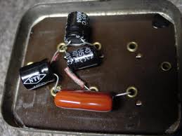
I've recaped 2 of the model 20s. The large filter can is not too bad to add in the new caps, right in the bottom cover. Snipping the wires back you should have enough room.
That would be the first step, and you just might receive stations after that step. Then, on to the other cap and out of spec resistors.
A fuse would be fine, in case something this side of the primary shorts out. But if something in the secondary like the filters shorts out, the fuse might not 'see' the current draw of the secondary, and continue to self destruct.
I have a couple of photos of how I installed the new caps, I just have to find the image in one of the older posts. You don't have to use electrolytics like I did, you can use film caps (non polarized) ad they will work fine. I used them on the second 20 I recapped.
So, you heard no hum but it had audio? Just white noise, or?
I'll check back.
Gary.


(This post was last modified: 05-16-2013, 10:45 PM by gary rabbitt.)
Posts: 4,682
Threads: 51
Joined: Sep 2008
City: Sandwick, BC, CA
If it were mine I would use the non polarized poly film capacitors inside that can just so you don't have to mess with it again, they take up more room then electrolytics but there is more then enough room in that can for them, though you may need to remove the old caps to do it.
Regards
Arran
Posts: 15
Threads: 2
Joined: May 2013
City: United States
It was "white noise", Gary.
Posts: 1,114
Threads: 14
Joined: Feb 2013
City: Irvington, NY
If you are getting white noise, it seems like everything past the detector stage is working. My guess is that you have an open winding on one of the RF coils. As Arran said, those coils are notorious for going bad due to corrosion of the fine gauge copper wire.
With the radio unplugged, you might try checking each coil winding for continuity with an ohmmeter. Here is a link to the schematic and service info for the set:
http://www.nostalgiaair.org/PagesByModel...029582.pdf
Posts: 15
Threads: 2
Joined: May 2013
City: United States
What value capacitors should I use in the power supply?
Posts: 4,682
Threads: 51
Joined: Sep 2008
City: Sandwick, BC, CA
The cap values are posted on the schematics on these pages:
http://www.philcoradio.com/tech/schema.htm
There is one for an early and another for a late Model 20 philco, I don't know which yours is.
Regards
Arran
Posts: 15
Threads: 2
Joined: May 2013
City: United States
Ok, the values I found on the schematic are 1.0, 1.0, 1.5 and 0.13
Posts: 1,957
Threads: 146
Joined: Jan 2013
City: Westland, MI
I agree with Arran...use the non-polarized poly film caps. The .13 might be a little hard to find, but a .15 will work just fine. I used 2 watt resistors for my replacements. I think you will find they will all have drifted up in value over the years. Most of mine were nearly double their resistance values listed. Take care. Gary
"Don't pity the dead, pity the living, above all, those living without love."
Professor Albus Dumbledore
Gary - Westland Michigan
Posts: 15
Threads: 2
Joined: May 2013
City: United States
The working voltage for these caps I believe should be 450 volts or higher.
Posts: 7,283
Threads: 268
Joined: Dec 2009
City: Roslyn Pa
If you go with the non polarized caps they come in a standard 630v rating. These will work great and last forever.
Terry
Users browsing this thread: 3 Guest(s)
|
|
Recent Posts
|
|
Jackson 715 not working
|
| Now that you posted the schematic, I don't know why that Sprague electrolytic cap is across the meter, as it is not indi...MrFixr55 — 05:51 PM |
|
HiFi (Chifi) tube amp build - but my own design.
|
| What may be lacking in the PP Tube amps may be the 2nd harmonics, which some, especially RCA back in the day called &quo...MrFixr55 — 05:32 PM |
|
Jackson 715 not working
|
| Usually in an emission tester, the tube under test is measured as if it were a diode. So, some testers connect all the g...RodB — 04:17 PM |
|
Restoring Philco 37-604C
|
| Yep. F5 is green, D5 is Red.
Red is Bad.
Green is Clean.morzh — 01:30 PM |
|
Jackson 715 not working
|
| I did start to do that but I stalled out because I could not figure out how the grid and plate get voltage. In this diag...daveone23 — 11:52 AM |
|
Restoring Philco 37-604C
|
| (Insert Homer Simpson "DOPF" Here.)
When all fails, look at the can. Took the Ron Ramirez advice, red Caig D...MrFixr55 — 09:23 AM |
|
Philco 91 Speaker Replacement
|
| From your text I am not sure if you intend to use the existing speaker with a resistor instead of the field coil.
It wo...morzh — 08:44 AM |
|
Philco 91 Speaker Replacement
|
| My field coil is bad. I am still hoping to find an original, but if I can't I will go with a fitting Philco speaker, 125...dconant — 08:34 AM |
|
Philco 91 Speaker Replacement
|
| As Rod said, it is OK to use a fitting speaker, and then look for an original one.
If you buy a Hammond 125 output tr...morzh — 08:15 AM |
|
Philco 91 Speaker Replacement
|
| Yes, I often have to substitute, then keep an eye out for an original. In the meantime, the radio is working and being e...RodB — 08:02 AM |
|
Who's Online
|
| There are currently no members online. |

|
 
|


![[-] [-]](https://philcoradio.com/phorum/images/bootbb/collapse.png)


