Thread Rating:
  • 0 Vote(s) - 0 Average
  • 1
  • 2
  • 3
  • 4
  • 5

Restoring a Model 19 Code 126
#1

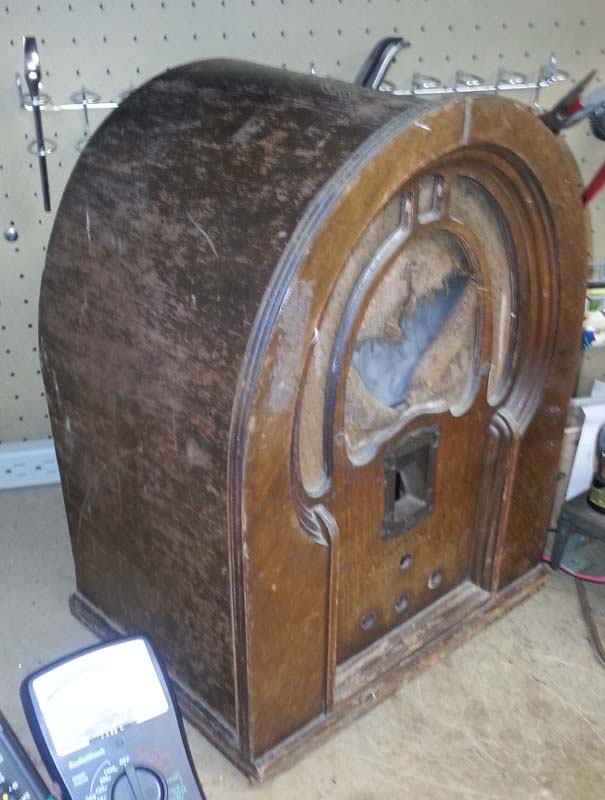
I have started to restore a Model 19 Code 126 Cathedral that I picked up at a thrift store over a year ago.  The electronics are really not in bad shape.  

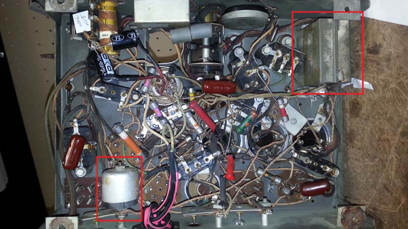
I have been spending a lot of time just tracing wiring and trying to understand where the parts are.  I have replaced a couple of the bakelite condenser blocks and trying to move onto the others.  I am not choosing to restuff, rather replacing each using a small terminal strip with the capacitors soldered in.  The space that it opens opens was is just too tempting.  It seems so much easier to trace the wiring.

BTW, in the picture, those maroon mylar caps are not mine.  It seems the previous owner tried experiementing by jumping several of the bakelite blocks with those capacitors.  I don't know what they strategy was there, but I will be removing those.

I have been reading everything I can on this site and others about this radio.

At this point, I have one question.  What is meant by "autodyne?"  Why did Philco use this design?  What were the advantages and disadvantages, and what can I expect to run into because of it?

Thanks!

Mark K8KZ


#2

Hi Mark & Welcome!!!
Well let me see the round thingy is the inductor for IF the wave trap. The square thingy is a can with bypass condensers usually 3 or 4 inside. The autodyne circuit was used because the pentagrid tube wasn't designed yet. Remember this 1931-32. It was also cheaper as it only use 1 tube instead of 2 (separate mixer/osc tubes).
You can expect to rewind the feedback winding on the osc coil. Very common problem but easy to repair. The bad feedback isn't because of the type the mixer it's a chemical/old age thing.
Terry N3GTE
#3

Welcome to the Phorum!!!
#4

Thanks for the welcomes guys!

I spend time on ARF, but have just started on Philco Forum, because this is my first Philco.

So the autodyne is the oscillator/mixer of the day that wasn't able to include a pentagrid, because it wasn't available yet?

So how does the oscillator/mixer work using the 36 tube? How is the design different from one using a pentagrid?

What do you think about following the available tech tip to replace the 36 with a 77 tube?

Mark
#5

Can't answer your 77 tube question but can tell you the bakelite block caps are not all that hard to stuff. Here's a thread showing how. The bypass cap can looks similar to one in a 60MB I'm working on. I was able to bend the metal tabs on one end, slide out the caps which were in a tar block but had a piece of fish paper around it so it just slid out. Then stuffed new caps in the can and closed it up. Don't know if the one in the 19 is the same though.
#6

Hi Mark
<So the autodyne is the oscillator/mixer of the day that wasn't able to include a pentagrid, because it wasn't available yet? 

Yes.

<So how does the oscillator/mixer work using the 36 tube? How is the design different from one using a pentagrid?


Well if you look at the diagram the input is on the control grid and it oscillace between the plate and cathode. The output is take off of the bottom of the osc coil.


<How is the design different from one using a pentagrid?

Alot more grids to use.


<What do you think about following the available tech tip to replace the 36 with a 77 tube?

Would most likily would give you a bit more gain as it is a little newer. Check the mu ratings.

GL
Terry
#7

Hello Mark,

I saw your post over at the other place.

Terry (Radioroslyn) has already answered most of your earlier questions, but I'll try to tackle the latest ones:

markmokris Wrote:So the autodyne is the oscillator/mixer of the day that wasn't able to include a pentagrid, because it wasn't available yet?

Right. Philco started using a tetrode autodyne circuit in the 2nd version 70, 3rd version 90, and model 51. This was early 1932, and the mixer-oscillator tube used was the 24 (later replaced by 24A). Philco's new radio line came out in June 1932, including the 71 and 91 which used the 36 tube for this purpose.

Models 19 and 89 came out around January 1933. Philco continued to use a 36 tube as a tetrode autodyne mixer-oscillator. The 6A7 pentagrid converter did not become available until later in 1933. With its shortcomings, the 6A7 was a much more efficient mixer-oscillator than using a tetrode as an autodyne oscillator.

For all of their technological innovations, Philco sometimes pinched pennies when they possibly should not have. For this reason, they never adapted the 6A7 to their model 19 or 89, although newer Philcos such as the 14, 17, 18 and even the lowly model 60 used the 6A7.

Quote:So how does the oscillator/mixer work using the 36 tube? How is the design different from one using a pentagrid?

Here's an extremely simplified answer. Anyone else here is welcome to elaborate on the following:

The 6A7's first two grids are dedicated to the oscillator circuit; G1 serving as a pseudo-triode grid and G2 as a pseudo-"plate" of the oscillator circuit. The RF signal is applied to G4. G3 and G5 are connected together and act as the screen grid for the entire tube.

G1 and G2 are part of the radio's oscillator tank circuit. The incoming RF via G4 mixes with the local oscillator signal produced by the oscillation in G1/G2. This mixing action produces numerous signals, but the radio only picks up the difference between the local oscillator and the incoming RF - the set's intermediate frequency (IF), which is 260 kc in the 19.

In the 36, the tube is oscillating 260 kc higher than the incoming RF signal which is applied to G1 of the 36. It looks simpler than the 6A7 circuit, and it is. Being a simpler circuit, it also makes the circuit less efficient and prone to troubles that can make the oscillator stop oscillating. Radios using the autodyne circuit are very sensitive to moisture absorption in their oscillator coils, and this will usually stop oscillation in Philco sets using the autodyne mixer while a mixer using a 6A7 might continue to function.

In other words, the autodyne circuit is more finicky.

Now that's a lot of verbiage not explaining things really well. Like I said, anyone is welcome to jump in and explain it better than I did.

Quote:What do you think about following the available tech tip to replace the 36 with a 77 tube?

I would not do it. The 89 and 19 sets can be made to work again using the original 36. You just have to work harder at it. Count on the "tickler" winding being bad, as Terry said earlier. Also count on having to bake the oscillator coil in an oven at 200 degrees (no hotter) for 30 minutes to drive out any moisture. Baking should be done before the tickler winding is rewound. If your resistor (10) is 15000 ohms, plan on replacing it with a resistor of 10000, 8200 or even 7500 ohms so that the circuit will oscillate properly.

If you're going to change the oscillator tube to something else, you might as well go all the way and change it to a 6A7. I would only recommend that to an experienced radio repairman, though.

Edit: I see Terry posted again as I was typing. Icon_thumbup

--
Ron Ramirez
Ferdinand IN
#8

Thanks for this great advice everyone. Especially the detailed information on oscillators from Ron.

I still have bakelite blocks to replace, but I have brought the set up using a variac. I do have audio, but no signal. I do not think it is oscillating. I think I will definitely try to get it working with the 36.

I am still checking all the coils and have not found anything open on the RF or Antenna coil. I think I have checked the oscillator coil, but not yet checked the tickler part.

Are you saying if the ticker is bad, it will be open? If it is NOT open, do I still have to remove the coil and bake it?

Mark
#9

(03-06-2015, 02:59 PM)markmokris Wrote:  Are you saying if the ticker is bad, it will be open? If it is NOT open, do I still have to remove the coil and bake it?

(1) Yes, and (2) I would highly recommend it. I have pulled 19 and 89 oscillator coils in the past and rewound only to find they would not work. That's when I started baking them. Since then, I have only had one coil refuse to work after baking and rewinding (out of several 19 and 89 sets restored).

--
Ron Ramirez
Ferdinand IN
#10

Welcome Mark, good luck with your 19.

Ron: Why the emphasis on baking before rewinding? I have been finding my 19 is a little reluctant to oscillate at times. I forgot to bake my oscillator coil when I rewound it. What would be wrong with just removing the coil assembly and baking it now?

Thanks,
#11

It depends on the insulating material you used underneath the tickler coil - some (such as Mylar tape) will melt and ruin the coil. Also, if you use hot glue to hold down the ends of the winding, the heat could also melt the glue, making the coil come loose.

--
Ron Ramirez
Ferdinand IN
#12

I was afraid it was something like that.

Thanks Ron.
#13

I wonder if baking at lower temp for lomger time could do the trick. I mean, the goal here is to expel the water absorbed by the bobbin, and any increase in temp results in water evaporating, the higher the faster.

People who do not drink, do not smoke, do not eat red meat will one day feel really stupid lying there and dying from nothing.
#14

Morzh,

I thought about that as well, but how do you know the temp at which things like tape start melting? If I knew that, I'd set the oven 30 or so degrees lower and bake longer. Just not sure what is safe. Is there a general consensus that 100F, or 125F, or 150F would be safe?
#15

Amother question for the experts: Has anyone tried sealing the coil form after baking to prevent future moisture absorption? If so, what did you use?


Users browsing this thread: 1 Guest(s)