09-07-2015, 11:19 AM
http://www.nostalgiaair.org/pagesbymodel...013797.pdf
What I see in the set and what I see on the parts layout don't seem to match here. It looks to me like filters C41, C55, C56 are switched on the parts layout. In fact, there seem to be several small part number errors on the part list as well.
It looks to me like the parts layout labels C41 as C54, C54 as C56, and C56 as C41.
On the set, the 8uf cap that has its negative side connected to the large end of R57 and the CT of the HV secondary also has the cardboard insulator and a 10K resistor connecting it to the electrolytic above it which should be the 16uf cap (part C41). The one on the position labeled as C56 has connections to the output transformer and C47.
On the parts layout, you can see the cap labeled as C41 has three rings on the outside which would indicate it is the one with the cardboard insulator, right?
Likely, this is documented somewhere, but I'm not finding it. Unless I hear otherwise from you Philco experts, I'm going with the layout I find in the set and following the schematic.
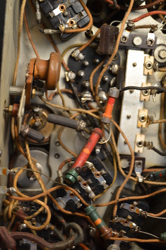
Here is a photo of what I see; that red wire going across the photo between the green and red resistors connects the e-cap on the left top to the CT and large end of the wire wound resistor:

The broken resistor is grey with silver at each end?
What I see in the set and what I see on the parts layout don't seem to match here. It looks to me like filters C41, C55, C56 are switched on the parts layout. In fact, there seem to be several small part number errors on the part list as well.
It looks to me like the parts layout labels C41 as C54, C54 as C56, and C56 as C41.
On the set, the 8uf cap that has its negative side connected to the large end of R57 and the CT of the HV secondary also has the cardboard insulator and a 10K resistor connecting it to the electrolytic above it which should be the 16uf cap (part C41). The one on the position labeled as C56 has connections to the output transformer and C47.
On the parts layout, you can see the cap labeled as C41 has three rings on the outside which would indicate it is the one with the cardboard insulator, right?
Likely, this is documented somewhere, but I'm not finding it. Unless I hear otherwise from you Philco experts, I'm going with the layout I find in the set and following the schematic.
Here is a photo of what I see; that red wire going across the photo between the green and red resistors connects the e-cap on the left top to the CT and large end of the wire wound resistor:
The broken resistor is grey with silver at each end?
Charlie in San Antonio


