Posts: 264
Threads: 51
Joined: Aug 2014
City: San Antonio, TX
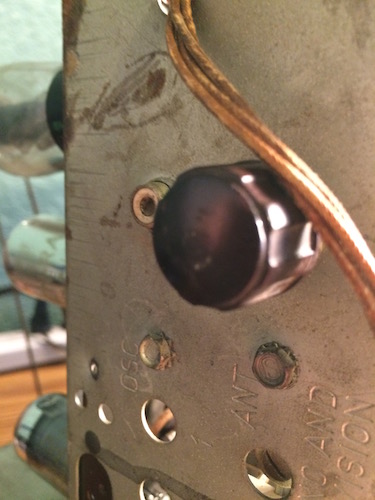
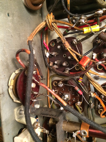
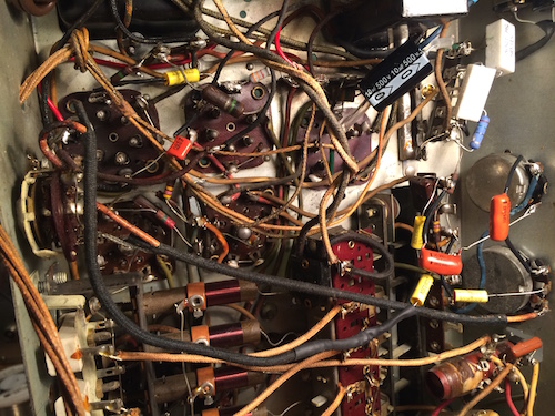
I'm guessing that the same technician who installed the Thoradson output transformer and liked to solder by placing leads next to each other and having at it with the solder gun might have installed this switch? It has an RCA jack, the switch seems to be a simple on/off kind of thing but doesn't click in place--it just rolls to its limits, shielded leads with the shielding soldered to the chassis, and it connects to the volume control through a second .003 uf 1000v cap and one of the IF transformers through a .01 uf cap.
The caps you see are mine...I replaced all of the caps, but I still need to trace all the circuits, and replace some wiring, yet.
I replaced all caps and out of range resistors, but I'm staring at this switch thinking I should take it and the extra .003 cap out of the set before I try to bring the set up on the variac.
Am I correct in thinking this is not a Philco part? Do you think I should get it out of there?
Note: Don't worry, the candohm is not in circuit...that ugly replacement is (I'm going to look around for a longer terminal).


Charlie in San Antonio
Posts: 347
Threads: 34
Joined: May 2007
City: Raleigh, NC
I'm reasonably sure that is not a Philco switch. The 41-285 certainly didn't have a factory phono input. Adding aftermarket RCA phono input jacks and switches to switch them (and disable the radio during phono operation) was pretty common.
You could restore the wiring to stock or you could leave it there in case you want to input audio from an iPod or similar device. If you do, trace out the wiring so you are sure what the switch actually does. A different switch with a clear switch point might be a good idea. It looks like it's probably a DPDT switch, which is needed to do the job right.
You might also check out Marcus and Levy, "Elements of Radio Servicing," chapter 12 for their advice on how to install aftermarket phono inputs correctly, just to check out whether yours is a good installation or figure out how to modify it so it is. Available here:
http://antiqueradios.com/archive.shtml.
John Honeycutt
Posts: 264
Threads: 51
Joined: Aug 2014
City: San Antonio, TX
Great advice. I'll look in my Marcus and Levy right away. I'm pretty comfortable with the switch, now. It makes no changes to the original circuit and its switching simply places the RCA jack in the circuit or shuts it out. I am keeping it out of the circuit while I troubleshoot the rest of the radio.
I've got the signal generator on it, now, and I'm able to get a strong audio tone from the top of the volume pot, so the output seems OK. I've measured all three IF transformers and have measurements similar to the schematic (3rd IF was difficult; I had to remove the push button electronics and got a good measurement on its primary winding, but couldn't figure out how to get the secondary, so I measured it AFTER the two resistors and got a number close to the added resistance of the winding plus the two resistors). The antenna coil and the oscillator coil measure good on all windings.
I can hear a modulated tone at 455KC from the plate and grid of the 1st detector, and from the plate of the oscillator, but get nothing from the oscillator grid which isn't surprising after I measured the voltages at the plate and grid of the oscillator. The plate was 10vdc and the grid was less than -1vdc (should be 40vdc on the plate--I can't find a suggested grid voltage, but should be about -8 according to Radio Museum).
I have to wait until tomorrow to look at it again, but I thought I might trace the filaments' voltages down the line, and look at what happens from C27 through to the plate of the XXL oscillator. I hope I don't end up replacing several mica caps around the band switch. Any suggestions would be appreciated.
Charlie in San Antonio
Posts: 4,611
Threads: 51
Joined: Sep 2008
City: Sandwick, BC, CA
There is no guessing at all with this, Philco, at least the U.S made Philco sets did not come with RCA phono jacks. I've also arrived at a policy of removing phono, or any other input or output jacks, for radios that did not leave the factory with them. The reason being is that they don't enhance the use of the radio much if at all, and often cause problems because of the crude and amateurish way that most are typically installed. I've seen so much butchery involved with putting those things in that I really don't offer any quarter to them anymore, so when I see one added to a new to me old radio, out it goes and back to original. There are plenty of factory built sets that came with a phono jack, and there are RF modulators for ones that don't.
Regards
Arran
Posts: 264
Threads: 51
Joined: Aug 2014
City: San Antonio, TX
It made sense to remove it. I did and replaced the .01 cap on the volume pot. I also found several issues and repaired them. The most important was at the junction of the 1 meg resistors R54 & R53. The leads were cracked, so I've replaced both resistors with new ones (the old ones had measured within tolerance, so I'd left them in place). I re-measured the output transformer from CT to each side and it is higher than the Philco part, but not by much (Philco is 170 and 190 ohms per side and the Thoradson is right at 210 or so per side). I measured each chassis ground and got continuity at each one. Retested the tubes...I wanted to see if there was an issue with the rectifier. All good. Lowest rating was a 7B7 at 60% with 50% as marginal on my Triplett.
Took some voltages, and voltages show some issues for sure:
junction of R30, R28, and R26=3.8v (should be 100v??)
pin 4 of the rectifier 84=217 (the pin the filter cap connects to)
grid of osc. XXL=0
C27A positive side=217 (should be 180v).
Just wrong. I wonder that I can hear the signal generator.
Charlie in San Antonio
Posts: 264
Threads: 51
Joined: Aug 2014
City: San Antonio, TX
Found it with some help from Norm. I went back to look at the candohm replacement I had made. And there it was.
Re-examining the candohm forced me to trace all of the attached leads to their components and I found the issue (which was a basic power supply problem). I had stupidly followed the original techs' lead dressing, and therefore I had C27A and C62 switched.
How it worked at all amazes me. I took the filters out, redressed them, and carefully followed the schematic to install them one at a time. Right now the set is singing beautifully on my bench. I'll let it run for a while to see if anything else comes up, but I'm impressed with the sound of this set. I bet when I get it back in the cabinet behind the grill cloth and bolted in, it will sound amazing.
Charlie in San Antonio


