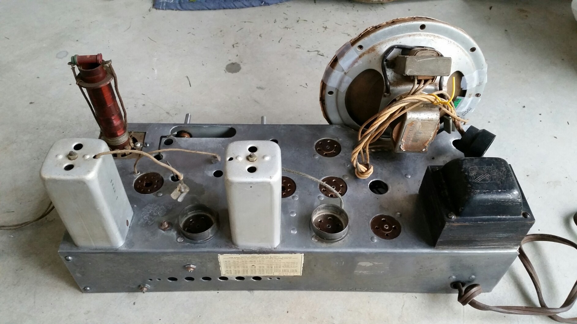
Next project: Western Air Patrol
Posts: 157
Threads: 13
Joined: Dec 2012
City: Seattle, WA
That chassis is looking nice, Ed!
I know what you mean about working from home keeping you busy. Same experience here.
Posts: 4,333
Threads: 407
Joined: Jun 2011
City: Boston
State, Province, Country: Massachusetts
Stuff seems to be doing well on rust. I like the dial scale, see it better outside of cabinet. Paul
Tubetalk1
Posts: 1,275
Threads: 44
Joined: Nov 2017
City: Menlo Park
State, Province, Country: CA
Had a mishap yesterday. one of the compression trimmers mounted on the back panel is seized - this has obviously been a problem in the past, as the screw was broken, leaving only half a slot. I have been able to take it out of the radio, and remove the screw , but it was very very hard to do, and resulted in the brass bushing separating from the ceramic body...
A replacement trimmer has been ordered, but I freed up the threads, and will try gluing the parts back together. It might just work... I don't like losing original parts, but when things are 80 years old, there are no guarantees.
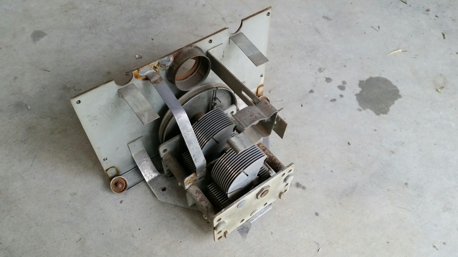
I did remove the tuning dial, and the derusting continues 
I don't hold with furniture that talks.
Posts: 1,275
Threads: 44
Joined: Nov 2017
City: Menlo Park
State, Province, Country: CA
It looks like the trimmer fix will be a good one. If not replacements are coming. New dial cord for the tuning control to tuner operation, but it will have to wait until the dial is returned to the radio. The pointer has its own cord, at much lower tension, and this seems to be fine.
The tuning shaft assembly was removed and disassembled, A good clean, deburring the retaining clips and re-lubing with fresh grease brought this back to silky smooth rotation again. A little oil was also applied carefully to the bandswitch and tone control shaft bushings. This made a nice improvement to their operability.
Not much else to report, save the last stages of the battle with rust. I hope to have some pictures to share tomorrow.
/Ed
I don't hold with furniture that talks.
Posts: 1,275
Threads: 44
Joined: Nov 2017
City: Menlo Park
State, Province, Country: CA
Hi Folks,
Made some more progress today, and also captured these pics. Cleaning and derusting. In fact, after the chassis picture was taken, I improved things quite a bit further.
Next up will be working out the best way to restuff the stud mount electrolytics. Chassis work will have to wait until a more powerful soldering iron arrives. Most of the decoupling caps are soldered directly to the chassis, and my 45 W iron won't be up to the job. Another good task in the mean time will be figuring out some of the power supply circuit and wiring, so that I can undo the previous repairs to meet the restuffed caps. There is nothing wrong with what the previous repairer did, and at first inspection, they didn't disturb too much, making it pretty straightforward.
Cheers
Ed


I don't hold with furniture that talks.
Posts: 1,275
Threads: 44
Joined: Nov 2017
City: Menlo Park
State, Province, Country: CA
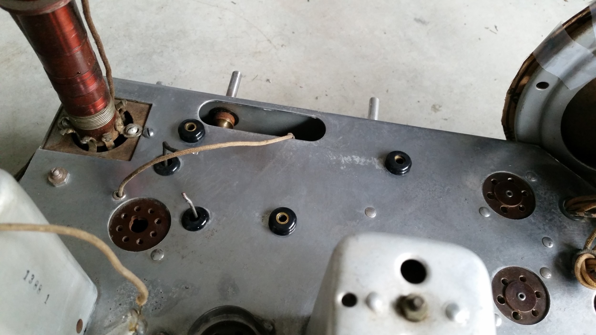
New Grommets on the chassis, ready for the tuner:

I don't hold with furniture that talks.
Posts: 1,275
Threads: 44
Joined: Nov 2017
City: Menlo Park
State, Province, Country: CA
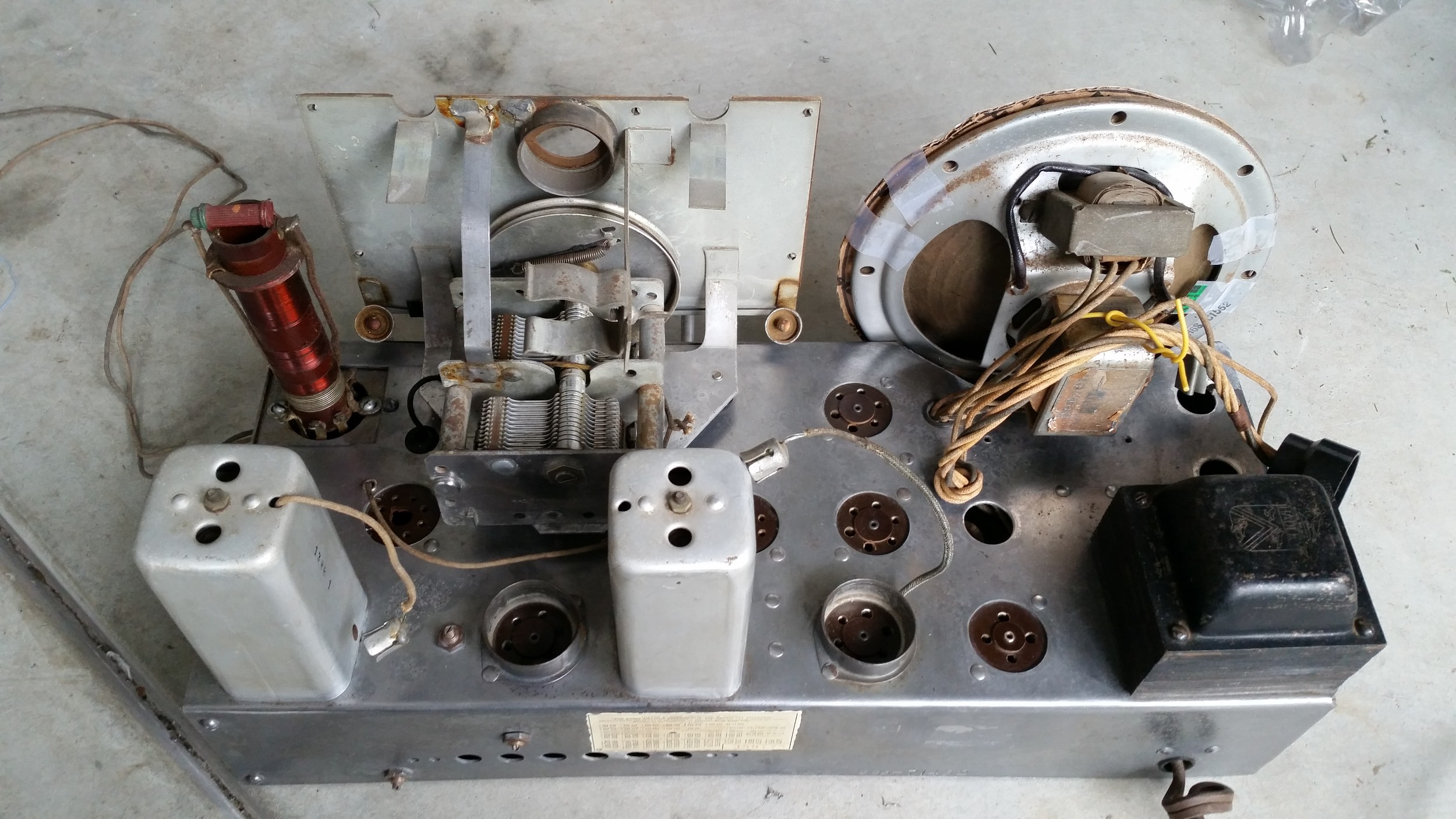
Back together, after a little extra cleaning here and there. I still need to replace the cord linking the tuning cap to the shaft on the chassis - cord arrived yesterday 

I don't hold with furniture that talks.
Posts: 1,475
Threads: 69
Joined: Nov 2012
City: Kansas city, MO.
Very nice work Ed. You did a great job on the chassis. 
Posts: 4,333
Threads: 407
Joined: Jun 2011
City: Boston
State, Province, Country: Massachusetts
What rust! Looks very fine, real progress. 
Paul
Tubetalk1
Posts: 1,275
Threads: 44
Joined: Nov 2017
City: Menlo Park
State, Province, Country: CA
Thanks guys 
More progress this afternoon - after a lot of fussing, the tuning drive cord was replaced. It proved very difficult to get the spring over the hook on the tuning cap drum. A glutton for punishment, I wasn't happy with the tension on the first attempt, so took it off, adjusted the cord length and went through the frustration for a second time. The set has tuning again with a good "feel" and no slipping.
After that, I traced out the power supply circuit. It is a pretty standard, with a cap straight off the rectifier, and another on the other side of the field coil. The Candohm forms the bias network on the return side of the circuit. Now I know which of the replacement caps are doing which task.
Cheers
Ed
I don't hold with furniture that talks.
Posts: 1,275
Threads: 44
Joined: Nov 2017
City: Menlo Park
State, Province, Country: CA
No progress for a day or two.. But my new iron arrived yesterday, so all the soldering jobs can be done properly.
I am half tempted to tack in some electrolytics, and power up on the dim bulb tester, just to see what we have got. Then again, I think going through the whole job properly is the best course. I have still not decided whether to cut open and restuff the thread/stud mount electrolytics, or replace them and add caps beneath the chassis. These are not like the twist locks, where they can be uncrimped and re-closed in the original way. It looks as if the tops were rolled over, and it would be hard not to make a mess of this visible area.
As always, I value the opinion of the experienced folks here. I'll post a picture of one of the caps later. They are tall, slender tubes, branded Solar.
Cheers
Ed
I don't hold with furniture that talks.
Posts: 1,275
Threads: 44
Joined: Nov 2017
City: Menlo Park
State, Province, Country: CA
A little work today before lunch. Replacement of the two most inaccessible caps beneath the RF coils and bandswitch assembly is complete. I had to unscrew and move the side panel to get in there, so it took a little time.
One thing I wanted to pay attention to is observing the outside foil connection for the new caps. But how to determine this with the new caps that are not marked? Easy. Clip the cap across the input to a cheap guitar amp. Note which lead is connected to ground. Grab the cap without touching the leads. If the hum increases, the cap's outer foil is connected to the signal line, if it doesn't increase, ground is connected to the outer foil. Then I mark a band around the appropriate end of the cap to note the outer foil lead.
More caps after an afternoon walk.
I don't hold with furniture that talks.
Posts: 1,275
Threads: 44
Joined: Nov 2017
City: Menlo Park
State, Province, Country: CA
A good afternoon so far 
All the paper caps were replaced. A number were themselves replacements, including some Sangamo types with plastic bodies but they still measured leaky. One or two of these were quite poorly soldered - sometimes just touched on to the connecting terminal. After that, I replaced the wires to the bulb sockets, which had frayed, and looked tatty. As yet, I've done nothing with the original electrolytics, so I decided to remove the old replacements, tidy things up a little and fit some temporary smoothing caps in order to enable a test power up.
Test one: Dim-bulb in series with the power, no rectifier in the socket. The bulb did its usual number of glowing a little, then dimming as the valve heaters come up to temperature. All valves showed the glow 
Test two: Dim Bulb, rectifier added, B+ monitored. The bulb behaved as before, and B+ rose, approached 300 v then fell as the circuits started to draw current. All good news. I played with the volume control. Not much going on, I thought, but eventually I realised there was a slight hiss and hum from the speaker. Crackles when the wave change switch was operated. A hint of changing noise when the tuning was moved, but no stations. Tuning up the Heathkit signal generator, I could hear the modulated signal as it swept through close to the IF, which should be at 460 kHz. Great!
Test three: Direct power. Without a knob on the waveband switch, it is hard to know the position. tuning around, I first heard the Morse Code output from my shortwave beacon, 13.555 MHz - aha! this is band C !. I switched down a band, and heard some noise, holding the short antenna lead. Then down again to broadcast. Stations and stations! Great volume, and the speaker is of nice quality.
Next thing will be to apply the golden screwdriver and attempt an alignment. That should be fun, as there's no service sheet, so I'll have to work out which trimmers are for which waveband and whether they are oscillator or aerial circuits, and for which end of the band. That's OK, I like these sort of challenges.
For now, I'm really happy that we have a working radio on the bench 
Cheers
Ed
I don't hold with furniture that talks.
Posts: 1,275
Threads: 44
Joined: Nov 2017
City: Menlo Park
State, Province, Country: CA
Getting there. I spent a while today working out which trimmers operate on which bands, and have that charted out. This enabled setting the oscillator tracking on all three bands. One easy method I like is to use an accurate receiver and pick up the local oscillator. Set the dial of the radio being serviced to a round number, set the listening radio to this value +IF and tune the oscillator trimmer until it is received.
One thing is that although broadcast reception is strong, I feel that the SW bands are weak. The higher band in particular, and this one also has a problem that the set pops into instability/motorboating at the high frequency end of the dial. I looked at the resistors around the 6A8, and found the oscillator grid leak has drifted high, now 120k from 60k nominal. I'll be changing that and retesting.
The antenna circuits on this radio seem not too responsive to their trimmers. That may be worth a look, as perhaps something is amiss here as well.
Problems, yes, but I am rather enjoying them 
I don't hold with furniture that talks.
Posts: 1,275
Threads: 44
Joined: Nov 2017
City: Menlo Park
State, Province, Country: CA
A busy day today, but I did get time to replace the suspect resistor. The squegging instability is gone from the high range of band three, and things seemed a bit better after a readjustment of the osc trimmers.
I don't hold with furniture that talks.
Users browsing this thread: 1 Guest(s)
|


