Posts: 1,181
Threads: 48
Joined: Oct 2017
City: Allendale, MI
Posts: 15,305
Threads: 530
Joined: Oct 2011
City: Jackson, NJ
Yeah, in my Westinghouse WR-212 someone also strapped 1000uF cap as the first filter.
I gutted it for its aluminum can.
People who do not drink, do not smoke, do not eat red meat will one day feel really stupid lying there and dying from nothing.
Posts: 7,215
Threads: 266
Joined: Dec 2009
City: Roslyn Pa
Nice job!! Reminds me of my 41-300, great player too!
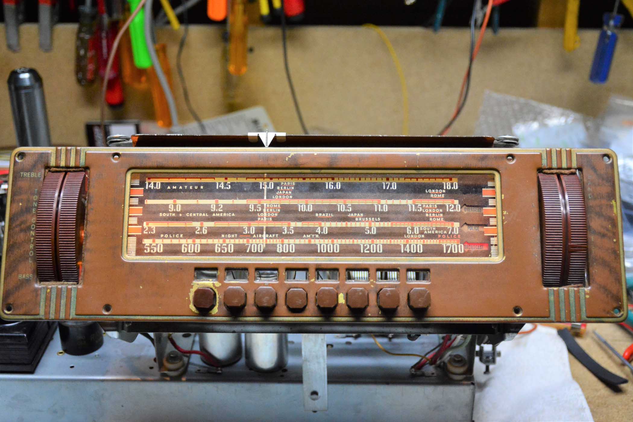
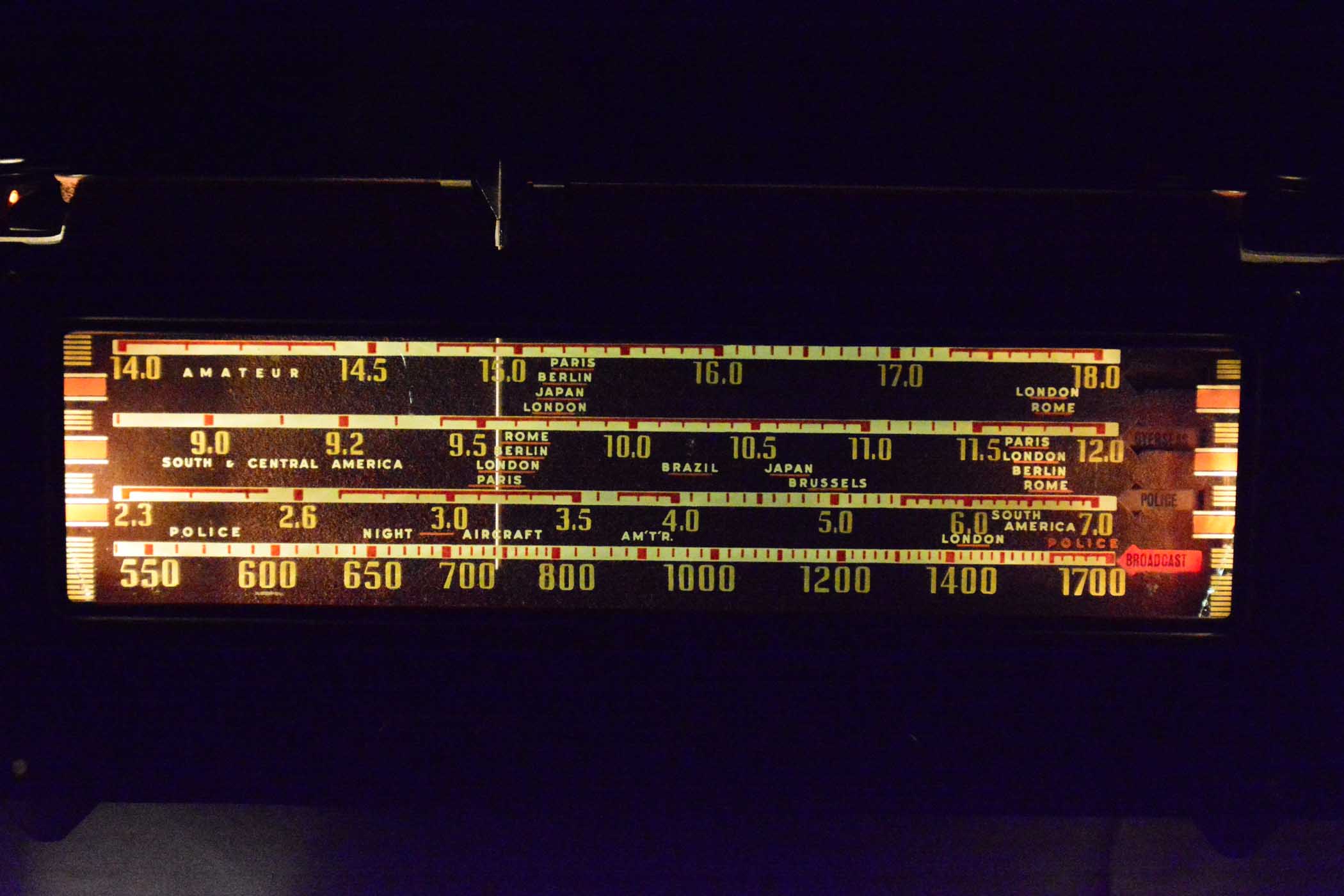
Was noticing that the frequency coverage skips the 160mtr and 40mtr ham bands (1.8-2.0mc and 7- 7.3mc). Back in the pre war days the 40mtr band was cw (Morse code) only so w/o some sort of bfo would but unreadable. SSB was abt 10yrs in the future, AM was the way to communicate via speech in those days.
Somewhere I did read a few posts abt the refinishing the dial bezel I'm pretty sure it was here on the Phorum. Took a quick look around and didn't see anything.
GL
When my pals were reading comic books
I was down in the basement in my dad's
workshop. Perusing his Sam's Photofoacts
Vol 1-50 admiring the old set and trying to
figure out what all those squiggly meant.
Circa 1966
Now I think I've got!
Terry
Posts: 1,181
Threads: 48
Joined: Oct 2017
City: Allendale, MI
Thanks Terry. I wasn't able to find anything either. I did find it curious that certain frequency ranges were skipped. At least the BC band goes up through 1.7 mhz. It would be interesting to see a history of wavelengths and their use over the years and how they changed from the 1920's through the present.
I will continue to look for hints on refinishing the bezel.
(This post was last modified: 03-16-2019, 11:13 AM by
rfeenstra.)
Posts: 1,181
Threads: 48
Joined: Oct 2017
City: Allendale, MI
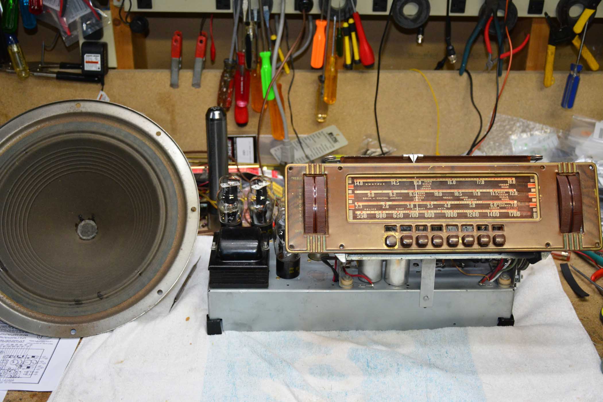
Does anyone know the speaker impedance for this radio? I needed to have the speaker reconed and they replaced the voice coil with an 8 ohm coil. I never measured the DC resistance for an approximation. It sounds good but if the original voice coil was similar to what Philco used in the earlier years, the power transfer could be poor.
Posts: 7,215
Threads: 266
Joined: Dec 2009
City: Roslyn Pa
Well Homer (Simpson) sez it's 4 1/2 ohms on my 41-300.
When my pals were reading comic books
I was down in the basement in my dad's
workshop. Perusing his Sam's Photofoacts
Vol 1-50 admiring the old set and trying to
figure out what all those squiggly meant.
Circa 1966
Now I think I've got!
Terry
Posts: 1,181
Threads: 48
Joined: Oct 2017
City: Allendale, MI
Thank you! I'll live with the 8 ohms.
(This post was last modified: 05-22-2019, 09:55 PM by
rfeenstra.)


