Posts: 13,776
Threads: 580
Joined: Sep 2005
City: Ferdinand
State, Province, Country: Indiana
Earlier this month, I picked up a nice Transitone (Philco) TP-5-I.
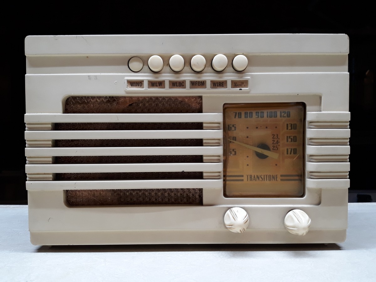
Last night, I began restoration work on it.
A look at the chassis:
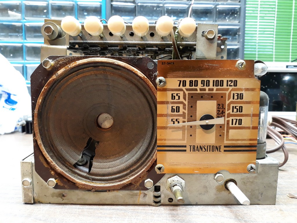
As you an see, a portion of the speaker cone is missing.
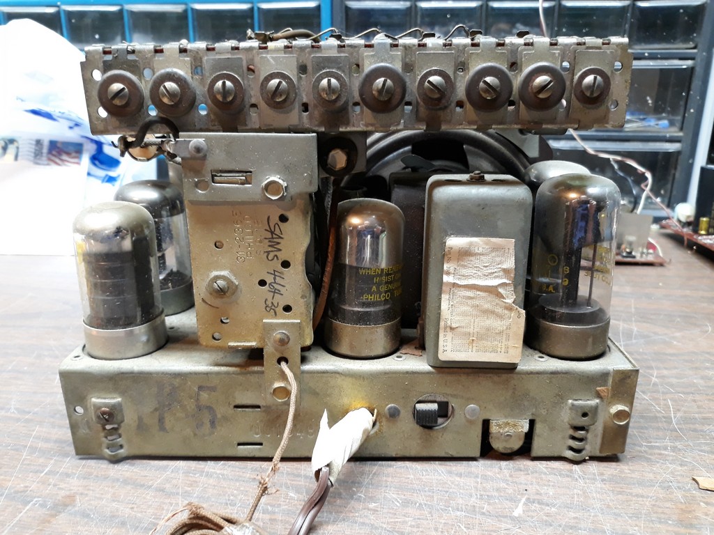
Rear view:
And how it looks underneath:
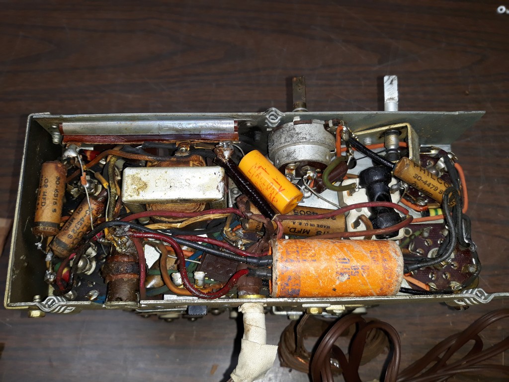
As you can see, it is jam-packed under the chassis. As I did with Sam's 40-501 Phonograph with Philco, I will take a radical approach to this chassis.
--
Ron Ramirez
Ferdinand IN
Posts: 13,776
Threads: 580
Joined: Sep 2005
City: Ferdinand
State, Province, Country: Indiana
The Transitone TP-5-I was introduced in January 1939 along with several other compact Transitone model table radios including the TH-4, TP-4-I, TH-5, TP-10, TP-11, TP-12, TP-14 and TP-15. These Transitones were much more compact in size than previous Philco table model radios, and they all used variations of the same stuffed, cramped chassis.
Since all of those wires are of the rotten rubber-coated variety, they all need to be replaced.
I have found that the best plan of attack is to remove as much as possible from underneath and start all over from scratch. Attempting to replace one wire at a time in a chassis as cramped as this will result in other wires getting damaged while trying to reach obscured solder terminals with other wires and components in the way.
So, last night...
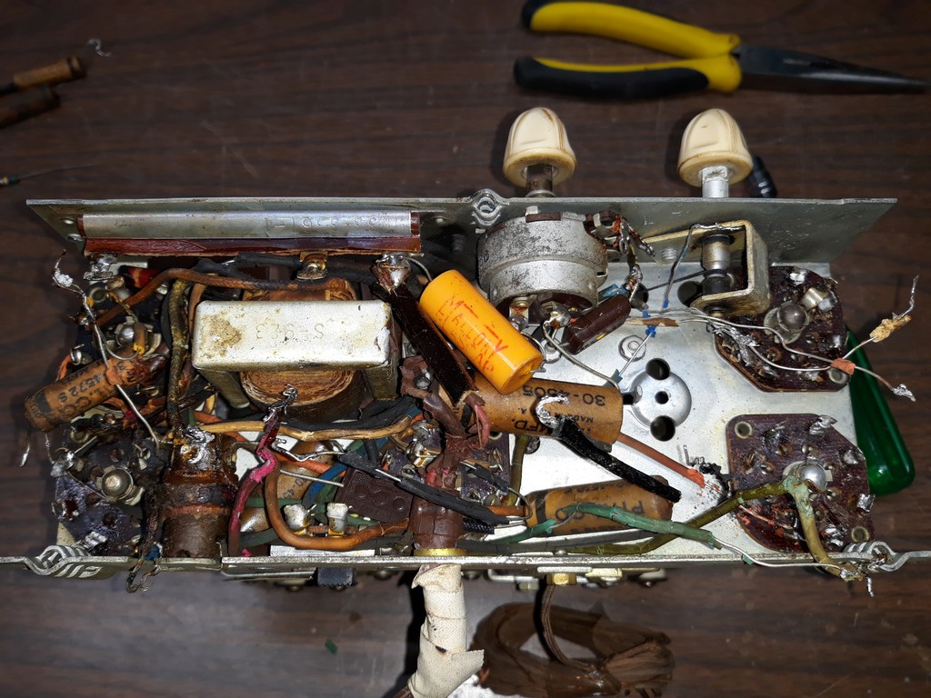
I began disconnecting and removing wires and components.
Tonight, I more or less finished up that job.
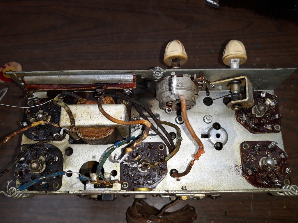
To be able to reach everything and replace the remaining wires, I will need to remove the speaker, the dial scale, and the pushbutton assembly. Removing the pushbutton assembly will also make it easier to clean.
Both IF transformers and the oscillator coil have been removed. Unfortunately, one of the oscillator coil terminals came off from the coil form while I was trying to remove one stubborn wire. The little wire from coil to terminal did not break, however, so this coil might still be usable. We shall see.
--
Ron Ramirez
Ferdinand IN
Posts: 1,475
Threads: 69
Joined: Nov 2012
City: Kansas city, MO.
Good looking little radio. With that rotted rubber wire makes sense to do it like you did the 40-501 chassis.
Posts: 11
Threads: 3
Joined: Aug 2018
City: Chicago
State, Province, Country: Illinois
Thanks for sharing! Looks like a lot of restoration work.
Posts: 244
Threads: 11
Joined: Oct 2011
City: Black Mountain, NC
Answers my question if those were loctal tubes....
Cossor 3468
GE 417A
Philco 118H
Radiola 17/100
Scott 800B6
Silvertone 6130
Stromberg 535M
Truetone D1952
Posts: 933
Threads: 140
Joined: Mar 2015
City: Lansdale
State, Province, Country: PA
Ron, Looks like the bottom of my PT-25 I assume its a basic design..
[Image: https://farm8.staticflickr.com/7845/4710...c596_b.jpg]
I had to do what you are doing.. Replace every wire..Just got it done today and put on bench.. Worked first time.. Doesn't seem to be to particulate about placement of wires.
Mine is not the greatest of rewire jobs.. But it works..
[Image: https://farm8.staticflickr.com/7921/4672...62a4_b.jpg]
Skip
Posts: 13,776
Threads: 580
Joined: Sep 2005
City: Ferdinand
State, Province, Country: Indiana
(03-22-2019, 03:58 PM)vecher Wrote: Ron, Looks like the bottom of my PT-25 I assume its a basic design..
(snip)
Mine is not the greatest of rewire jobs.. But it works..
And that is all that matters. 
Yes, the same basic chassis was carried over into 1940, many 1941 models and even a few 1942 Philco Transitone models.
--
Ron Ramirez
Ferdinand IN
Posts: 1,845
Threads: 140
Joined: Jan 2013
City: Westland, MI
What a crammed little chassis! I would probably be looking for a liquor bottle half an hour into it! Take care, Gary
"Don't pity the dead, pity the living, above all, those living without love."
Professor Albus Dumbledore
Gary - Westland Michigan
Posts: 13,776
Threads: 580
Joined: Sep 2005
City: Ferdinand
State, Province, Country: Indiana
Tonight's progress:
I removed the speaker, dial pointer and dial scale.
I unmounted (but did not completely remove) the pushbutton assembly. I've even started replacing wires. I found that the antenna coil tests OK so that is a good thing. I'll have to replace the original hank of antenna wire as it is badly frayed.
--
Ron Ramirez
Ferdinand IN
Posts: 4,335
Threads: 407
Joined: Jun 2011
City: Boston
State, Province, Country: Massachusetts
Though tough to work on I always think on the little sets not everyone could afford the top of the line. Wonder what the original owner listened to on that set..............
Paul
Tubetalk1
Posts: 289
Threads: 42
Joined: Jan 2014
City: Jeffersonville
State, Province, Country: PA
Hi Ron
Are you rewiring it exactly as it was from the factory? I've read that the wire routing paths were crucial to ensuring the best performance and deviating from it could introduce hum.
Thanks
Paul
Posts: 1,845
Threads: 140
Joined: Jan 2013
City: Westland, MI
I think I see another candohm tutorial in the future as well...
"Don't pity the dead, pity the living, above all, those living without love."
Professor Albus Dumbledore
Gary - Westland Michigan
Posts: 13,776
Threads: 580
Joined: Sep 2005
City: Ferdinand
State, Province, Country: Indiana
Paul (WyTex) - The new wiring probably won't end up being run exactly as it was from the factory, but will be close enough. I've done this before to a couple of those cramped little chassis and they turned out just fine. 
Gary - I checked the Candohm and the resistances are slightly higher than listed on the schematic, so it is going to be reused. It should not be too difficult to replace if need be.
--
Ron Ramirez
Ferdinand IN
Posts: 13,776
Threads: 580
Joined: Sep 2005
City: Ferdinand
State, Province, Country: Indiana
Rather than actually working on the radio this evening, I put together an under-chassis view of the parts which will help me get everything back together...and will hopefully help others as well.
Here it is.
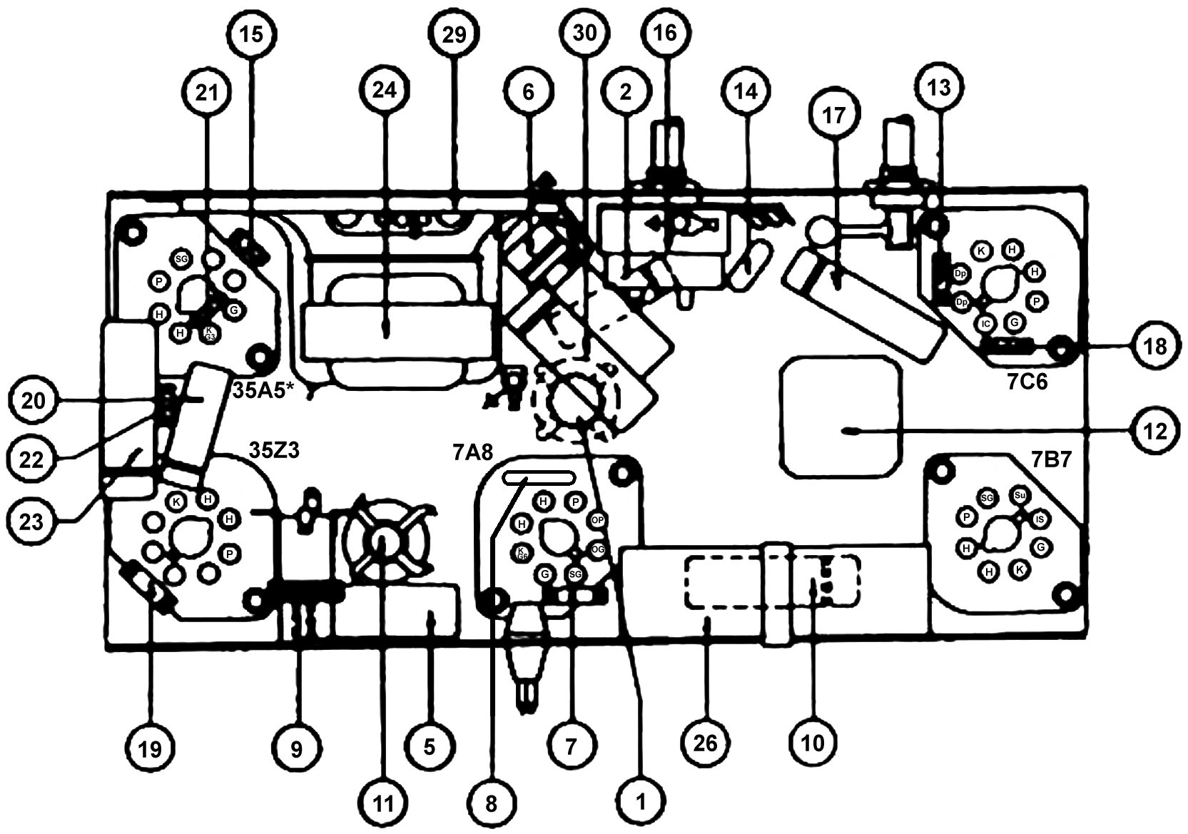
Why Philco never published one of these for their little Transitone/Philco Transitone models, I do not know...
Helpful hint: Right-click on the image above and select View Image. You can then see it in full size if you wish. You can then right-click that and download the image if you want to.
--
Ron Ramirez
Ferdinand IN
Posts: 15,306
Threads: 531
Joined: Oct 2011
City: Jackson, NJ
Good diagram, quite Philco style 
What do you use, Ron, to draft? A CAD or some Office Draw? Doesn't look like drawn by hand.
People who do not drink, do not smoke, do not eat red meat will one day feel really stupid lying there and dying from nothing.
Users browsing this thread: 1 Guest(s)
|


